
Simple Telephone Timer Circuit PCB

The telephone timer circuit typically consists of a few essential components: a microcontroller or timer IC, a piezo buzzer, an LED, and a power supply. The microcontroller or timer IC is programmed to count the elapsed time from the moment the user activates the timer. When the call connects, the user presses a switch to start the timer.
The piezo buzzer serves as an audible alert, producing a sound at the end of each minute to notify the user that a minute has elapsed. The LED provides a visual cue, flashing in synchronization with the buzzer. This dual alert system ensures that users remain aware of their call duration, promoting efficient communication and cost savings.
The circuit may also include a power management section to ensure that it operates efficiently and conserves battery life. A small capacitor can be used to smooth out power supply fluctuations, while a resistor limits the current to the LED and the buzzer, protecting them from excessive current that could lead to damage.
In terms of layout, the components should be arranged to minimize the length of the connections, reducing noise and potential interference. The microcontroller should be placed centrally to easily connect to the buzzer and LED. Additionally, the circuit should have a user-friendly interface, with clearly marked activation buttons and indicators for the timer status.
Overall, this telephone timer circuit is a practical solution for users looking to manage their call duration effectively, contributing to cost savings in telecommunication expenses.Telephones are reaching its death point all over the world. however there is more than 350 million mobile phone users in india, but there are tremendous number of telephone users are there also. Well, this telephone timer is designed to help saving by controlling unnecessary time taken during pone calls.
This simple timer circuit is better in its accuracy because it is manually put on by the user when the call connects at the other end. The piezo buzzer provided in the circuit makes a beep along with an LED flash during every passing minute. The time will not so accurate, but there is not more than 2-3 seconds variation. you have to put ON the timer at the moment when call starts. Then it will do the job of alerting during each minute to suppress your conversation and save money. 🔗 External reference
Related Circuits
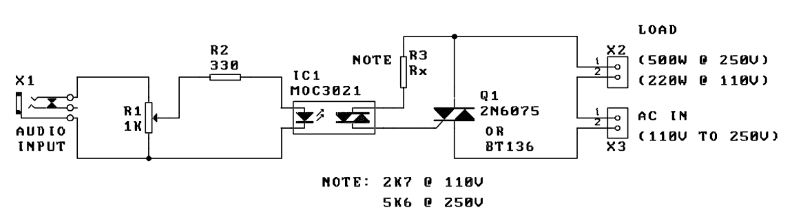
A music-to-light modulator is a circuit which controls the intensity of one or more lights in response to an audio input. The problem in older circuits is that there was a direct electrical connection between the lights using mains...
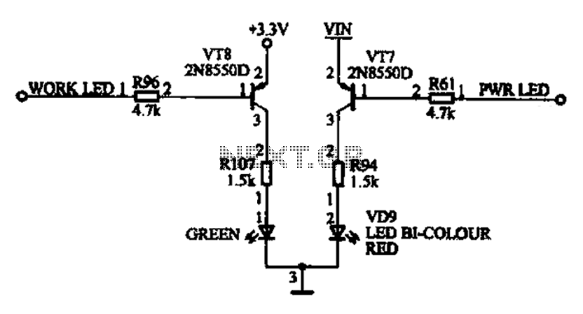
The ACER PM02 MP4 machine features a voltage status indicator circuit. When power is supplied, a red LED illuminates, indicating that the device is powered on. Upon entering operational mode, a green LED lights up. The voltage status indicator circuit...
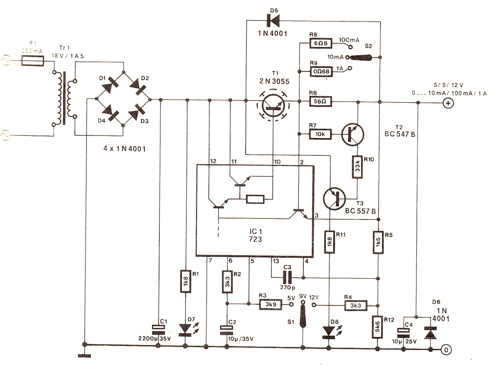
The output voltage can be increased easily by placing a resistor in parallel with Ra until it reaches precisely 5.0 V. Switches S1 and S2 are preferably SPDT types with a center position, but three-way rotary switches can also...
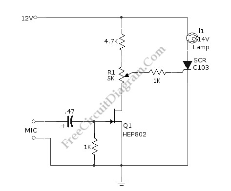
This simple circuit illustrated in the schematic diagram activates the switch using sound. It can be utilized for various applications, such as automatic (sound-controlled) disco lights or car LED light shows. The transistor Q1 amplifies the audio from the...
The circuit on this page is for a simple light detector circuit board that has 8 detectors that can be used with visible or infrared light systems. The detectors use LM339 voltage comparators as the active element. Phototransistors or...
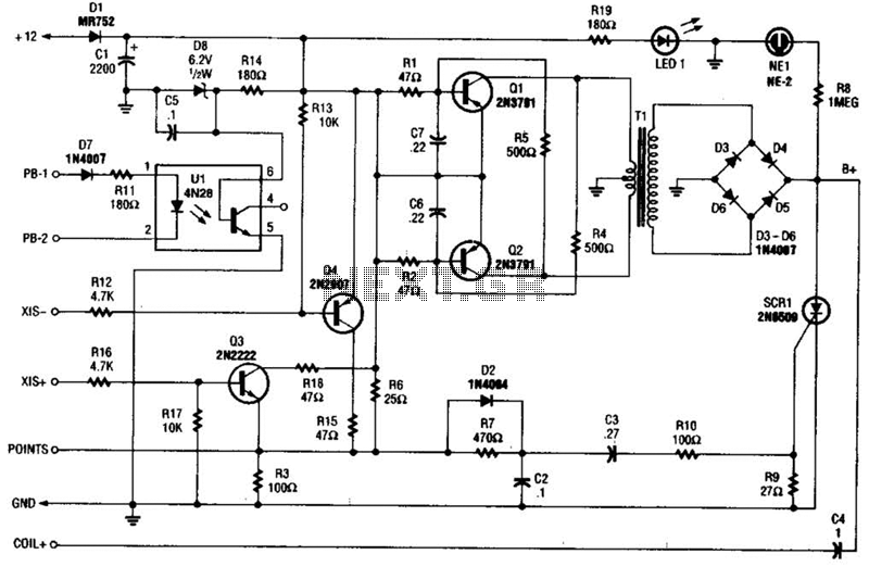
At the core of the CD4-MX is an astable multivibrator, constructed using transistors Q1 and Q2, which drives step-up transformer T1. The output from T1 is rectified by diodes D3 to D6 and utilized to charge capacitor C4. Upon...