
Sound-Activated Lamp circuit diagram (Relay/Switch)
")
The circuit operates by detecting sound levels through a microphone, which converts sound waves into an electrical signal. The microphone's output is typically a low-level audio signal, which is insufficient to drive most electronic components directly. Therefore, Q1, a transistor, is employed as an amplifier to boost this signal.
When sound is detected, the microphone generates a corresponding electrical signal that is fed into the base of the transistor Q1. The transistor is configured in a common-emitter configuration, which provides significant voltage gain. The amplified output from the collector of Q1 can then be used to drive a relay or another switching device, allowing for control of larger loads such as lights or sound systems.
The resistor R1 plays a critical role in setting the threshold for activation. By adjusting R1, the user can fine-tune the circuit's sensitivity to sound, ensuring that it only activates in response to desired sound levels. If the signal at the base of Q1 exceeds approximately 0.7 volts, the transistor will enter saturation, allowing current to flow from the collector to the emitter, thus activating the connected load.
Additional components may be included in the circuit for enhanced functionality. For instance, a capacitor could be added in parallel with R1 to filter out high-frequency noise, ensuring that only significant sound events trigger the circuit. A diode might also be incorporated to protect the circuit from back EMF generated when using inductive loads like relays.
This sound-activated switch circuit is versatile and can be adapted for various applications, including sound-activated decorations, automatic lighting systems, and interactive displays, making it a useful tool in both hobbyist and professional electronic projects.This simple circuit shown int the schematic diagram actives the switch using sound. We can use this circuit for various applications, such as automatic (sound-controlled) disco light or car s LED light show. The Q1 amplify the audio from mic. The R1 is used to adjust the peak of signal to greater than about 0.7 volts, act as sensitivity adjuster.
A certain l.. 🔗 External reference
Related Circuits

This circuit illustrates a remote control circuit diagram using RF technology without the use of a microcontroller. Features include a simple remote control circuit that operates via radio frequency. The remote control circuit operates by transmitting signals through radio waves,...
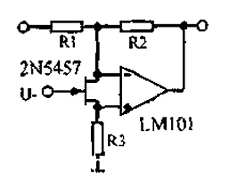
A 1.53 voltage-controlled gain amplifier (VGA) utilizes a FET connected between the two inputs of the operational amplifier (op-amp) as a voltage-controlled resistance. The resistance changes linearly with voltage and varies from several dozen square ohms, exhibiting excellent control...
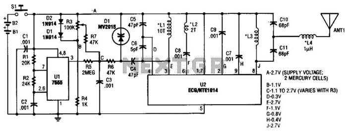
This transmitter can be utilized for multiple applications. An INS8048L microprocessor produces various codes based on keypad inputs. These codes are modulated onto a 40-kHz carrier frequency. Additionally, Q1 drives infrared LEDs LED1 and LED2. The transmitter circuit primarily consists...

To prevent the failure of electric contact pressure thermometer contacts due to singeing, it is advisable to enhance the contacts, as illustrated in Fig. 11-60. Specifically, the output termination table for DC control utilizes two two-way thyristors or a...
This sensitive FM radio tuner is an ideal circuit for hobbyists who wish to construct their own tuners rather than purchasing a pre-assembled product. The FM radio tuner circuit is designed to receive frequency modulation signals, providing a clear and...
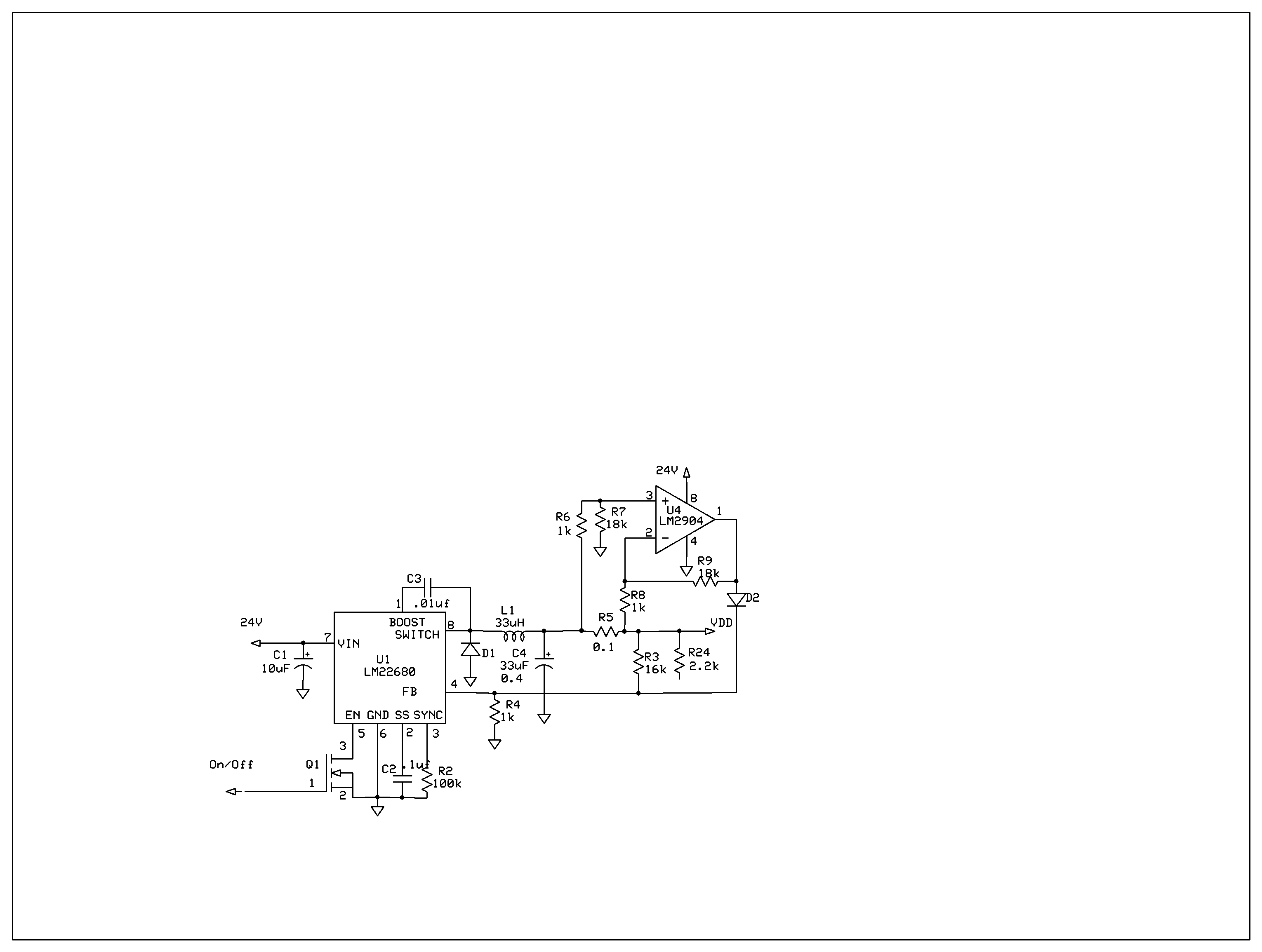
The product requires a voltage-controlled, current-limited power supply. Various switcher chips have been used with an op-amp to provide feedback for a current sense voltage to the feedback pin. Currently, an LM22680 is in use, but it has shown...