
Simple Transistor Reflex Receivers

This reflex radio circuit utilizes a minimalist approach to achieve functionality, drawing inspiration from classic two-transistor designs. The circuit is built around two transistors that serve as amplifiers, with the first transistor receiving the radio frequency (RF) signal and the second transistor functioning as a driver for the audio output. The inter-stage transformer plays a crucial role in coupling the output of the first transistor to the input of the second, thereby eliminating the need for additional amplification stages.
The antenna coil consists of 20 turns of wire, wound around four insulated posts. This configuration is designed to maximize the effective length of the antenna while maintaining a compact form factor. The choice of materials for the posts, such as nylon or insulated bolts, ensures that there is no unintended grounding or signal loss, which is vital for maintaining signal integrity in RF applications. The dimensions of the coil are flexible, allowing for some customization based on the enclosure used for the radio.
Signal coupling is accomplished using a secondary winding of two turns, which is placed directly atop the main 20-turn winding. While this method simplifies the construction of the circuit, it introduces additional capacitive coupling. This capacitance can adversely affect the tuning range of the circuit, particularly when utilizing a standard 365 pF variable capacitor, which is commonly used in radio frequency tuning applications. Careful consideration must be given to the layout and winding technique to mitigate these effects and optimize performance.
Overall, this reflex radio project exemplifies a blend of simplicity and functionality, drawing from historical designs while incorporating modern insights into RF circuit design. The result is a compact and effective radio capable of receiving a variety of signals with minimal components.This reflex radio project was inspired by Robert Bazian 's design. His reflex radio is the "darndest" thing I have seen and his spectacular results inspired me to come up with my own version! These designs are similar to two-transistor circuits used in some ancient Japanese "Boys Radios" except that the inter-stage transformer directly drives the speaker.
The antenna coil is just 20 turns wrapped around four insulated posts as seen in the photos and shown in the diagram below. I used nylon posts but ordinary bolts covered with tubing would work fine. The dimensions are not particularly critical; those shown happen to fit inside the case I chose. The signal is coupled to the receiver by two turns wrapped right on top of the 20 turns. This winding technique is simple but it has the drawback of having more than desirable capacitance and that limits the tuning range with a standard 365 pF variable ca 🔗 External reference
Related Circuits

This wiring circuit diagram is designed for providing power to specific rooms in a home or office during a power supply failure. It ensures continuous power supply to devices such as laptops and computers in those particular rooms, especially...
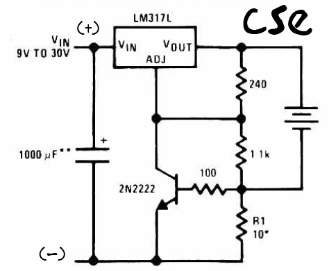
This is a straightforward charger designed for 9V to 30V batteries, primarily operated by the IC LM317L and a 2N222 transistor. It utilizes direct input DC voltage, and a recommended capacitor of 1000µF is included for filtering the output...
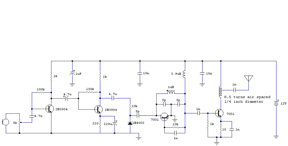
This circuit generates an FM modulated signal with an output power of approximately 500 mW. The microphone preamplifier is constructed using two 2N3904 transistors, with audio gain controlled by a 5 kΩ preset resistor. The oscillator is a Colpitts...
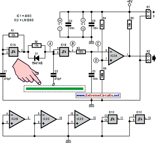
Capacitive touch sensors operate based on the electrical capacitance associated with the human body. When a finger approaches the sensor, it establishes a capacitance to the ground, typically ranging from 30 to 100 pF. This phenomenon can be utilized...
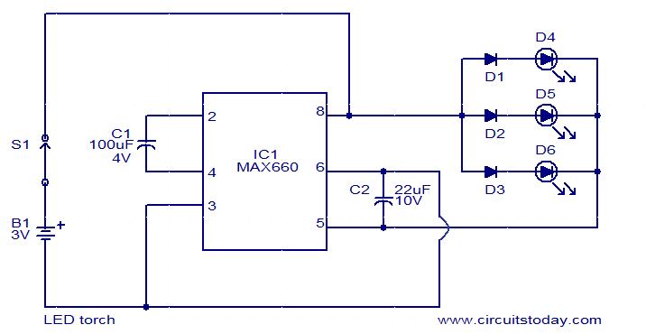
This circuit is a simple LED torch utilizing the MAX660 integrated circuit from MAXIM semiconductors. The MAX660 is a CMOS monolithic voltage converter IC capable of driving three bright white LEDs connected in parallel to output pin 8 of...
A single gate (open collector, non-inverting) generates a simple one-shot pulse that lasts for a duration equal to t, plus the RiCi time constant. R2 serves as a pull-up resistor to maintain the input of the gate high while...