
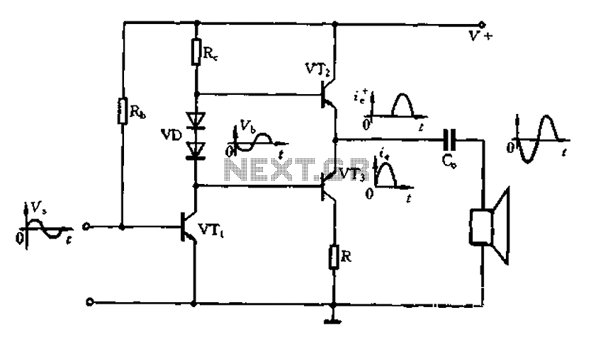
Simple Two Way Communication Intercom Circuit Schematic diagram

The intercom circuit operates on a dual-channel basis, allowing users to communicate in both directions. The core components include the LM384 and NE5534 integrated circuits, which are critical for audio processing. The LM384, known for its ability to deliver significant audio power, is ideal for driving loudspeakers in intercom applications. Its output power capability, combined with a 15-volt power supply, ensures that the audio signal remains strong and clear.
The NE5534 preamplifier plays a vital role by boosting the audio signal before it reaches the LM384. This preamplification is crucial for maintaining audio fidelity, especially in environments with background noise. The gain setting of 11 for the LM384 ensures that the output signal is sufficiently amplified for clear communication.
The use of switches S1 and S2 allows for seamless toggling between talking and listening modes. This design enables each loudspeaker to function as both a microphone and a speaker, depending on the switch configuration. The ability to add more speakers enhances the system's versatility, making it suitable for various applications, from small residential setups to larger office environments.
Overall, the intercom circuit is a straightforward yet effective solution for two-way communication, leveraging the capabilities of the LM384 and NE5534 to deliver reliable audio performance. The design simplicity and scalability make it an attractive option for users seeking an efficient intercom system.Intercom or Inter communication circuit is a two directional communication system. It provides a reliable communication line and is extremely easy to implement. The circuit is prepared by an amplifier, two switches and two loudspeakers. We can extend this circuit by adding more number of speakers with the help of switches. IC LM384 works as a powe r output amplifier in this intercom circuit. LM384 provides almost 2 watts of audio power via 15 volts supply voltage. This intercom circuit diagram is very simple and practical circuit capable of using intercoms for homes, office intercom. If switch S1 is in Talk` contact, L1 functions as a Microphone. If it is in Listen` position, L1 functions as a Speaker. (Similar case applicable in L2 also. ) IC NE5534 works as a Pre Amplifier which boosts the Audio signal before applying to the LM384 amplifier section.
The gain of the LM384 op amp amplifier is set to 11. By changing the switch positions of S2 in to Talk` position and S1 to Listen` position, L2 get connected to the input section and L1 connected to output section. 🔗 External reference
Related Circuits
The Class A power amplifier exhibits low distortion; however, it suffers from low efficiency and limited output power, prompting the design of Class B power amplifier circuits. The Class B amplifier operates by shifting the operating point of the...
This is a HiFi pre-amplifier circuit diagram with low noise output. It offers a very wide frequency range from approximately 10 Hz to 100 kHz, which enhances audio performance. The HiFi pre-amplifier circuit is designed to amplify weak audio signals...
The voltage to be sampled is applied to the input of R2, a 100K linear taper potentiometer, while the other end of R2 is grounded. Consequently, the signal level that is sent to the buffering level shifter U1-A and...
Uploaded with ImageShack.us Uploaded with ImageShack.us Uploaded with ImageShack.us Inquiry regarding experiences with specific circuits. In this context, the inquiry pertains to the performance and functionality of certain electronic circuits that have been shared via an image hosting service. The...
Hello everyone, I am not well-versed in electronics, so I would appreciate it if someone could create a diagram for me. I would like to modify a circuit so that it can dial a number using speed dial and...
This circuit, based on the NE555 timer, activates and deactivates the IC output using a momentary switch. It functions similarly to a mechanical latching relay, but resets to its initial state when the power supply is turned off. This...