
555 Momentary Switch Circuit

The NE555 timer is configured in a bistable mode, allowing it to function as a flip-flop. In this configuration, the momentary switch serves as a trigger to toggle the state of the output. The circuit comprises two transistors (Q1 and Q2), a capacitor, and a pull-up resistor, which work together to create a latching effect without the need for mechanical relays.
When the momentary switch is initially pressed, the capacitor charges quickly, causing Q1 to turn on. This action pulls the voltage at pins 2 and 6 down, which in turn causes the output at pin 3 to go high, illuminating the LED. The high output state remains until the switch is pressed again. Upon the second press, Q2 is activated, which pulls pin 4 low, effectively resetting the circuit to its original state and turning off the LED.
The design is particularly suitable for applications where a temporary activation is required, such as in automotive lighting systems, where the driver may want to activate a light briefly without maintaining the switch in the on position. The absence of mechanical components not only reduces wear and tear but also allows for a more compact and reliable circuit design. The use of a pull-up resistor is critical as it ensures that pin 4 is held high when Q2 is off, preventing any unintended toggling of the output state. The overall simplicity and effectiveness of this circuit make it a valuable solution for various electronic applications.Based on NE555 this circuit turns on and off the IC output by a momentary switch. In other words it works as a mechanical latching relay, but the circuit backs to the start condition when you switch off the power supply. This feature is often required in automotive devices. No relay contacts are used, infact I connected the output to a led. Once t he momentary switch circuit is supplied the output (pin 3) keeps off because pin 2 and 6 are at half voltage. When the button is pressed Q1 turns on within a fraction of second because of the capacitor, while Q2 keeps off.
By switching on Q1 leads pin 2 and 6 to low voltage, then the output gets high. When the button is pressed again Q2 switches on and leads pin 4 to low voltage (I used a pull up resistor), then the circuit takes the start condition. 🔗 External reference
Related Circuits
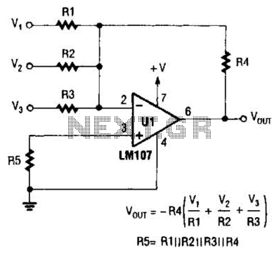
The output of Ul is the sum of Vv, multiplied by the ratio of Rx to Rv, RJRV, and respectively. Resistors R1, R2, and R3 are selected as required for individual gains. Additionally, R4 influences the gain of all...
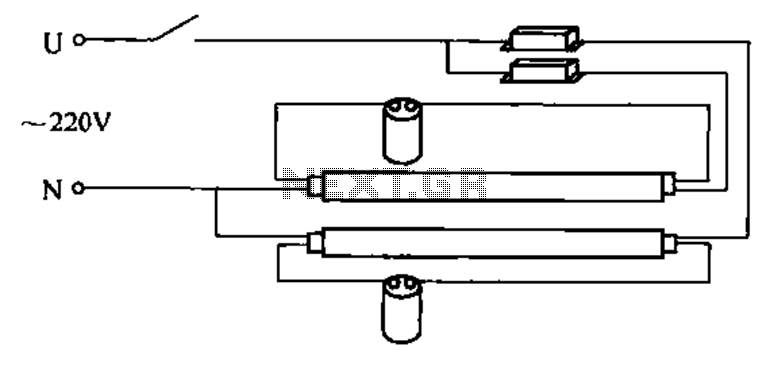
A double tube fluorescent lighting circuit is illustrated. In certain situations, a single tube light may not fulfill the lighting requirements, necessitating the use of double tube lighting. The physical installation is depicted in the circuit of a double...
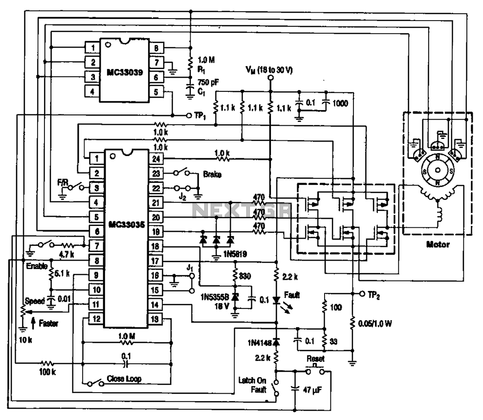
The brushless DC motor control circuit utilizing the MC33035 and MC33039 chips employs a combination of control circuits as illustrated in the figure. The primary components include the MC33035 motor control chip, the MC33039 brushless motor adapter, field effect...
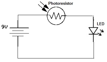
A simple photoresistor circuit will be constructed to demonstrate the operation of a photoresistor, which activates the circuit in the presence of light and deactivates it in darkness. This circuit connects a photoresistor to an LED. When the photoresistor...
AVC - The circuit regulates the volume line automatically, providing an output voltage of approximately 4 volts peak to peak. This voltage remains consistent. The Automatic Volume Control (AVC) circuit is designed to manage audio levels dynamically, ensuring a stable...
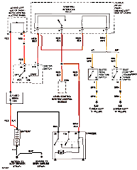
This circuit below shows an electrical circuit applicable for the Audi A4 Quattro 2004 model year. Component: Transmission, Anti-lock Brakes Circuit. The electrical circuit for the Audi A4 Quattro 2004 model year encompasses critical components such as the transmission system...