
HiFi Pre$2damp circuit diagram

The HiFi pre-amplifier circuit is designed to amplify weak audio signals while maintaining high fidelity and low noise levels. The circuit typically consists of several key components, including operational amplifiers (op-amps), resistors, capacitors, and possibly a power supply circuit.
The operational amplifiers serve as the core amplification element, configured in a non-inverting or inverting mode depending on the desired gain and input/output characteristics. The choice of op-amps is crucial, as low-noise types are preferred to minimize unwanted noise in the output signal.
Resistors are used to set the gain of the amplifier and to provide feedback within the circuit. The values of these resistors can be adjusted to achieve the desired amplification level, ensuring that the output signal matches the requirements of downstream audio equipment.
Capacitors play a vital role in coupling and decoupling stages of the circuit. They block DC components while allowing AC signals to pass, which is essential for audio applications. Additionally, capacitors are used for filtering purposes, helping to smooth out fluctuations in the power supply and reducing noise.
The frequency response of the pre-amplifier is critical for achieving optimal audio performance. A range from 10 Hz to 100 kHz allows for the reproduction of low bass notes as well as high-frequency details, ensuring a full and rich sound experience. Careful selection of component values and circuit layout can help maintain this wide frequency response while minimizing distortion and phase shift.
In summary, the HiFi pre-amplifier circuit is engineered to provide high-quality audio amplification with low noise and a broad frequency range, making it suitable for various audio applications. Proper design and component selection are essential to ensure that the pre-amplifier meets the high standards expected in modern audio systems.This is a HiFi pre-amplifiercircuit diagramwith low noise output. Very wide range frequency from about 10Hz until up to 100Khz will be gained by this preamplifier for maximumaudioperformance. 🔗 External reference
Related Circuits
The LM1875 is a monolithic audio amplifier that provides very low distortion and high-quality performance for audio amplifier projects. The LM1875 delivers 20 watts into loads of 4 Ohms or 8 Ohms. The LM1875 audio amplifier is designed for applications...
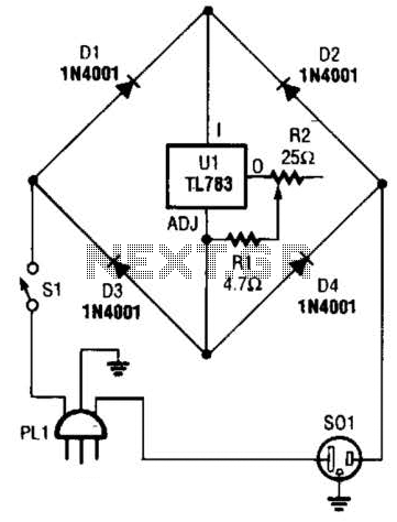
A current control circuit for temperature regulation of a soldering iron utilizes a high-voltage integrated regulator, TL783 (U1). With the specified component values, this circuit is suitable for use with a soldering iron rated at 25 W or less. The...
This is a straightforward and effective LED circuit that can be powered directly from an AC mains supply ranging from 100 volts to 230 volts. The circuit can serve as a mains power indicator or a night lamp. Resistors...
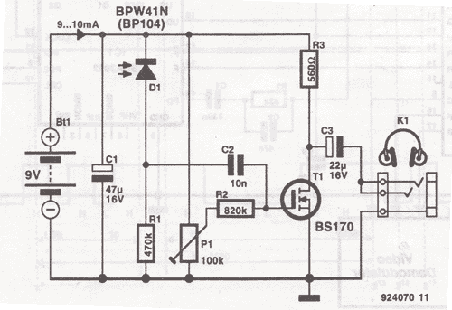
This wireless headphones transmitter ensures quality reception over a distance of 2 meters. The oscillator frequency ranges from 1750 kHz to 3500 kHz, and for the antenna, it... The wireless headphones transmitter operates within a frequency range of 1750 kHz...
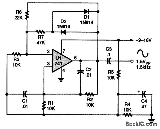
A 741 operational amplifier is configured within a Wien-bridge audio sine-wave oscillator circuit. The components C1, C2, R1, and R2 are responsible for determining the operating frequency of the circuit. By utilizing NPO capacitors and metal-film resistors, the oscillator...
This circuit utilizes a relay to control a water pump, enabling automatic level control for a water reservoir or well. The shorter steel rod acts as the "water high" sensor, while the longer rod serves as the "water low"...