
Simple UPS
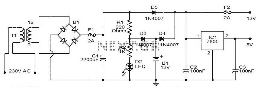
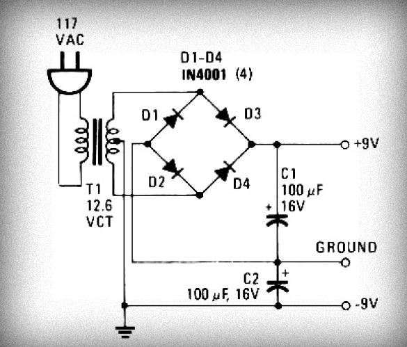
The UPS circuit operates by converting AC mains voltage to a lower DC voltage suitable for charging batteries and powering devices. The transformer T1 plays a critical role in this process, stepping down the mains voltage to 12V AC. The bridge rectifier B1 then converts this AC voltage to pulsating DC. The smoothing capacitor C1 is essential for reducing the ripple voltage, ensuring a more stable DC output.
When the mains supply is active, the system allows for battery charging via diode D3, which prevents backflow of current. The output voltage regulation is achieved through the use of a linear voltage regulator IC, which in this case can be a 7805 for 5V output or a 7812 for 12V output, depending on design requirements. The presence of diodes D4 and D5 ensures that the system can seamlessly switch between mains supply and battery operation without damaging components.
The inquiry about the inverter's function in stepping up the voltage from 12V to 220V indicates an interest in understanding the additional components required for this conversion. Typically, an inverter circuit would include an oscillator to generate a high-frequency AC signal, followed by a transformer designed to step up the voltage to the desired level. The absence of these components in the provided schematic suggests that the UPS design may be focused solely on DC outputs without an integrated inverter section.
Regarding battery health assessment, it is advisable to monitor individual battery voltages and internal resistances to evaluate their condition. This can be accomplished using a battery management system (BMS) that provides data on each cell's performance, allowing for more accurate health assessments.
The request for a circuit capable of delivering 16V unregulated and 12V regulated output at 1.2A necessitates careful consideration of component ratings. The choice of a 16-0 3A step-down transformer is appropriate, as it provides sufficient current capacity for the application. The use of a 7812 voltage regulator instead of a 7805 will effectively yield the desired 12V output, provided that the input voltage remains within the acceptable range for the regulator.
The discussion about removing the 220-ohm resistor (R1) for improved battery charging efficiency raises important considerations. While it may seem beneficial to eliminate this resistor to increase current flow, it is essential to evaluate the impact on the charging circuit's functionality. Removing R1 could potentially lead to excessive charging currents, which may damage the battery or reduce its lifespan. It is critical to ensure that the charging circuit maintains appropriate current levels to prevent overcharging while still providing efficient operation.
In conclusion, the circuit design and modifications should be approached with caution, ensuring that all components are appropriately rated and that the system operates within safe parameters to maintain reliability and performance.This is the circuit diagram of a simple UPS that can deliver 12V unregulated and 5V regulated DC. The transformer T1 steps down the mains voltage to 12V AC and then the bridge B1 rectifies it. The rectified signal is smoothed by the capacitor C1. When the mains supply is available the battery will be charged via diode D3 and the regulator IC gets s upply via diode D5. 12V and 5V DC will be available at the output terminals. When mains supply is not available the battery supplies current to the regulator IC and to the 12V DC terminal through diode D4. Also, the diode D3 blocks reverse flow of current during battery mode. Capacitors C2 and C3 acts as filters. i want to know how the inverter change the 12v to the 220v cos i can not see the step up transformer in the circuit and more so the inverter circuit is not clear to me.
sir i want to see the battery bank circuitry inside the ups and how we can estimate the ups health and this is possible to estimate batteries health individually or we can estimate the health of the banks as a whole. thanks for quick reply. I need a circuit of 16v unregulated and 12v regulated with atleast 1. 2A as output. I`m planning to use 16-0 3A step down transformer. So i`m planning to use 7812 IC instead of 7805 ic inside the circuit to get 12v 1. 2A as the output. My questions are 4)Also i want to add a battery over charging protector circuit as in. its for 6v battery. i want to use it for my 12v battery with 16v transformer o/p. just tell me what all to be changed. Plz kindly answer all the 4 questions. Plz sir, i`m in very confused situation. I know i`m torturing you, even though i`m thanking you for your valuable support. Thanks will u plz reply via email ganeshrnet{@}live{. }com thanks for quick reply. I need a circuit of 16v unregulated and 12v regulated with atleast 1. 2A as output. I`m planning to use 16-0 3A step down transformer. So i`m planning to use 7812 IC instead of 7805 ic inside the circuit to get 12v 1. 2A as the output. My questions are Sir, i wish to know whether the removal of R1 which is 220ohms for better charging of the 12v battery I think the battery when connected in serial with a resistor will reduce the charging efficiency So if we can remove and adjust the resistor, it will be better no Is there any problem in that Will it affect auto charging or will it reduce the output voltage to the unregulated 12v lead, while in power mode condition And also I`ve designed my own circuit diagram removing R1 220ohm.
the link to the described diagram is : please see it and reply via email ganeshrnet{@}live[. ]com 🔗 External reference
Related Circuits
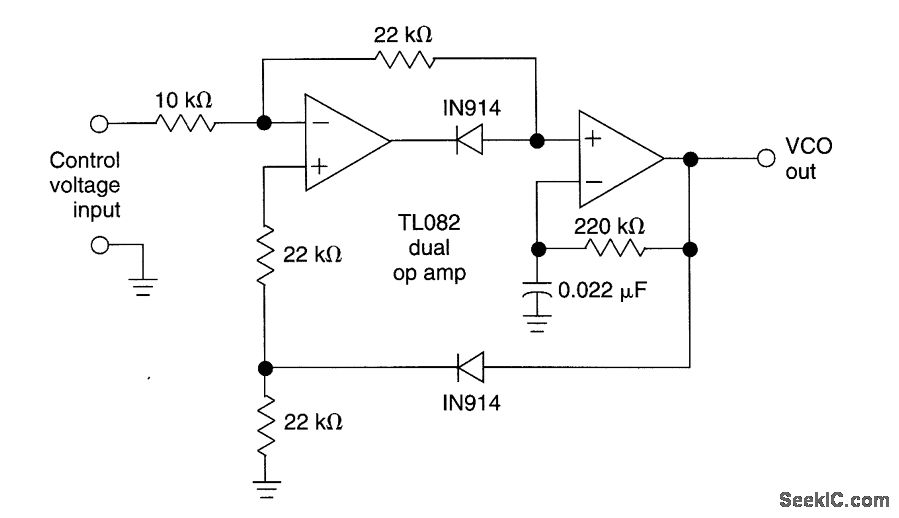
This circuit utilizes a dual operational amplifier (TL082) to create a voltage-controlled oscillator (VCO). The specified component values allow the output frequency to range from 100 Hz to 10 kHz when the input control voltage varies between 0.05 V...
A VU-meter is a common instrument typically found on audio Hi-Fi amplifiers, designed to display the instantaneous power delivered to the speakers. It is usually connected at the amplifier's output, in parallel with the speaker. The term "VU" stands...
The schematic below illustrates a simple LED flasher circuit. This circuit utilizes three LEDs that begin to blink or flash upon receiving a 9-volt supply. It is straightforward in design, employing a self-flashing LED (LED 1) to trigger the...
The first two components are passive elements, while the operational amplifier (op-amp) is an active element. The passive elements are two-terminal components, whereas the op-amp is a three-terminal component. A resistor controls the current flowing through it when a...
A DIY GSM jammer schematic diagram designed specifically for GSM1900 frequencies ranging from 1930 MHz to 1990 MHz. The GSM1900 mobile phone network is utilized in the USA, Canada, and most South American countries. This cell phone jammer is...
Initially, voltage from AC 220V or 110V enters the transformer, which reduces it to 12V AC. This AC voltage is then rectified using either four diodes or a bridge rectifier to convert it to DC voltage. The resulting DC...
Warning: include(partials/cookie-banner.php): Failed to open stream: Permission denied in /var/www/html/nextgr/view-circuit.php on line 713
Warning: include(): Failed opening 'partials/cookie-banner.php' for inclusion (include_path='.:/usr/share/php') in /var/www/html/nextgr/view-circuit.php on line 713