
Simple Utility Mixer

The described mixer circuit is designed to combine various signal types, ranging from audio frequencies to high-frequency radio frequency (RF) signals. The circuit operates using two Field Effect Transistor (FET) amplifier stages, which are configured to work together with a shared load resistor, denoted as R2. This configuration is crucial for the mixing process, as each FET amplifies its respective input signal, which is then developed across the common load resistor.
The unique aspect of this circuit is its ability to produce a difference signal due to the cancellation effect that occurs when the two amplified signals interact at the load resistor. This principle is fundamental in many RF applications, where mixing different frequencies is essential for modulation and demodulation processes.
The flexibility of the circuit is noteworthy, as it can handle a wide range of input levels and impedances, making it versatile for various applications. The low-impedance output is particularly advantageous, allowing the circuit to drive most tuned circuits or transistors without significant signal degradation.
For users seeking to adjust the gain of the circuit, it is recommended to modify the value of the load resistor R2. By reducing R2 to 220 ohms, the gain can be decreased without compromising the mixer’s fundamental mixing capabilities. This adjustment allows for greater control over the output signal, catering to specific application requirements while maintaining the integrity of the mixing function. Overall, this mixer circuit represents a robust solution for combining signals across a broad frequency spectrum while ensuring low noise and effective gain characteristics. Here"s an interesting mixer circuit. With it you can effectively combine signals from audio to high-fre-quency RF. Als o, as a special bonus, this circuit will provide some gain at a low noise figure. The inputs can be of almost any level or impedance, and the output (low-Z) will drive most tuned circuits or transistors. Basically, the device consists of two similar FET amplifier stages with a common load resistor (R2). Each FET develops a signal across this resistor, a form of cancellation occurs, and a difference signal results.
If you want less gain, try reducing R2 to 2 200-. This modification will not affect the mixing ability.
Related Circuits
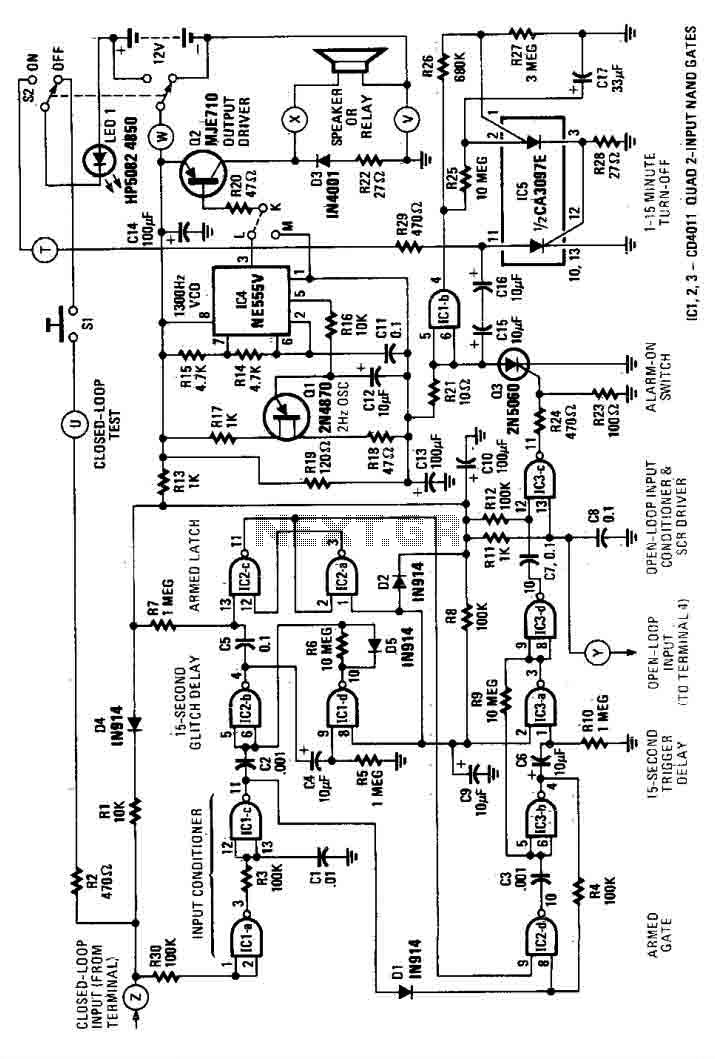
This house alarm circuit features both open and closed loop sensors and includes a self-shutdown function. The delay after triggering can be adjusted between 1 minute and 12 minutes, while the delay before triggering is set at 13 seconds....

This circuit diagram represents a simple electronic combination lock utilizing the IC LS7220. The circuit is designed to activate a relay for controlling any device (on and off) each time a specific combination of four digits is entered. It...
Simple Surround Sound Decoder. Introduction This surround-sound decoder is based on the Hafler principle, first discovered by David Hafler sometime in the early 1970s. The original idea. The simple surround sound decoder utilizes the Hafler principle to create an immersive...
This Total Harmonic Distortion (THD) circuit differs from typical designs as it operates at a standard frequency of 1000 Hz while also being tunable between 970 Hz and 1030 Hz. It features an adjustable Q factor ranging from 0.3...
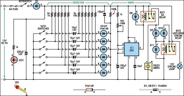
This simple alarm circuit is designed for use in a combined garage and rumpus room. It can be assembled on Veroboard and utilizes a single integrated circuit (IC) along with a few inexpensive components. The circuit is based on...
This circuit is designed for ease of tuning. When the pulse voltage reaches 6V, all transistors operate as open switches, eliminating the risk of battery shorts. The pulse voltage source V5 can be substituted with a 555 astable circuit....