
Touch delay switch circuit diagram CD4013 composed

The described circuit employs two D flip-flops from the CD4013 series, which are configured to create a touch-sensitive delay switch. This arrangement allows for the activation of a load, such as a light or machine, with a delay after the initial touch input. The first flip-flop is configured to capture the touch input, while the second flip-flop is utilized to determine the state of the output after the delay period.
The power self-locking function ensures that once the switch is activated, it remains in the 'on' state until it is intentionally reset. This is achieved by feeding back the output of the second flip-flop to the input of the first, creating a latch effect. The circuit can be designed to include additional components such as resistors and capacitors to set the timing for the delay period, allowing for customization based on application requirements.
In practical applications, this circuit can be beneficial for scenarios where a momentary touch is required to activate a device, such as in lighting systems, where the user may prefer a delay before the light turns on, or in machines where a delay is necessary for safe operation. The simplicity of the CD4013 D flip-flops allows for reliable performance in various electronic projects, making it a suitable choice for touch-delay switch designs. As shown mainly by the touch-delay switch one pair of D flip-flop CD4013 composed, it can be used in some machines power switch, delay switch is also used as lighting, it also has power self-locking function, circuit as shown in FIG.
Related Circuits
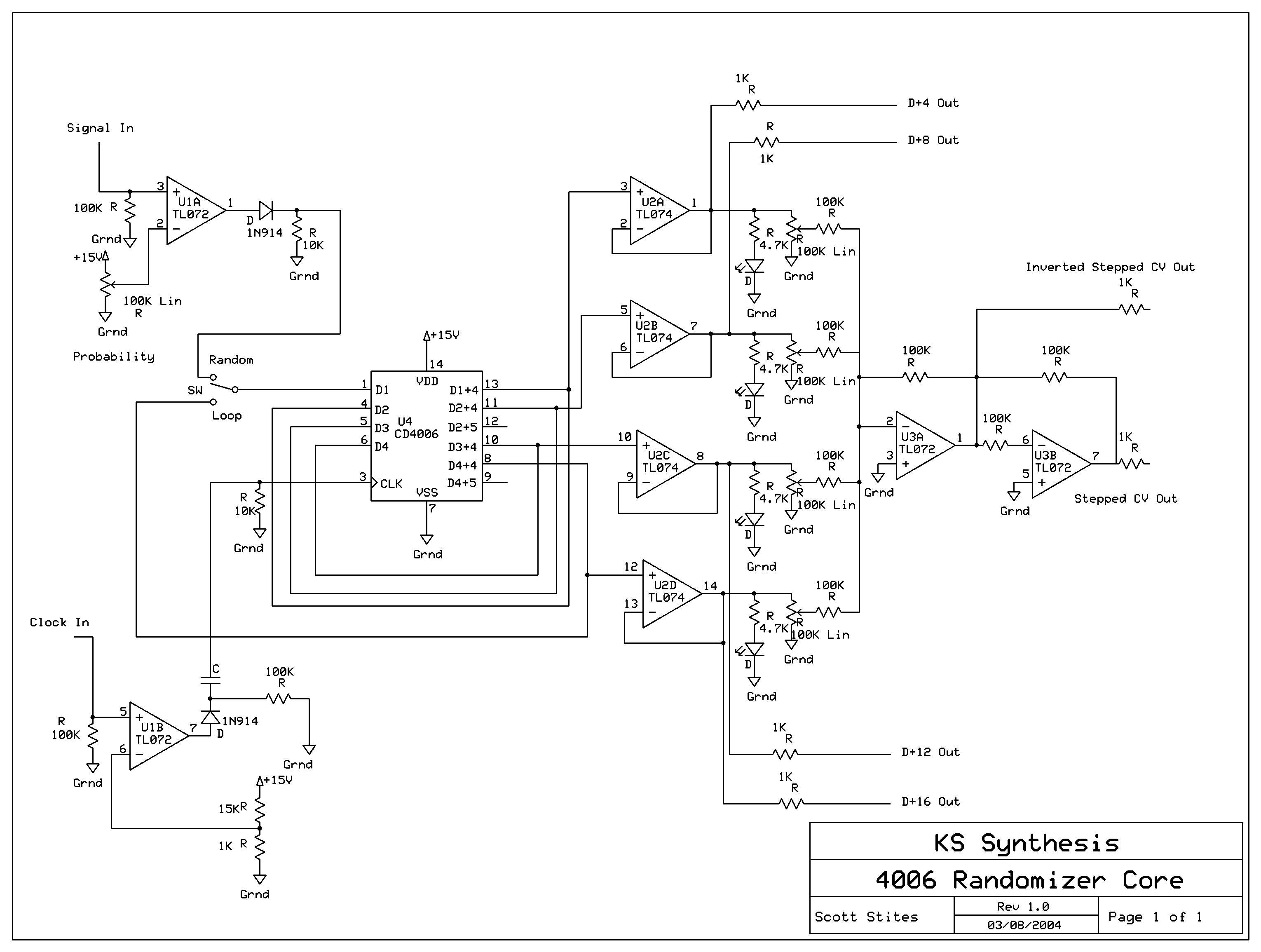
The mechanics of the Quantized Random Voltage function are intriguing. Instead of having fixed quantization steps for each output of the 4006 shift register, it is proposed to make the voltages adjustable through potentiometers. The Quantized Random Voltage function...
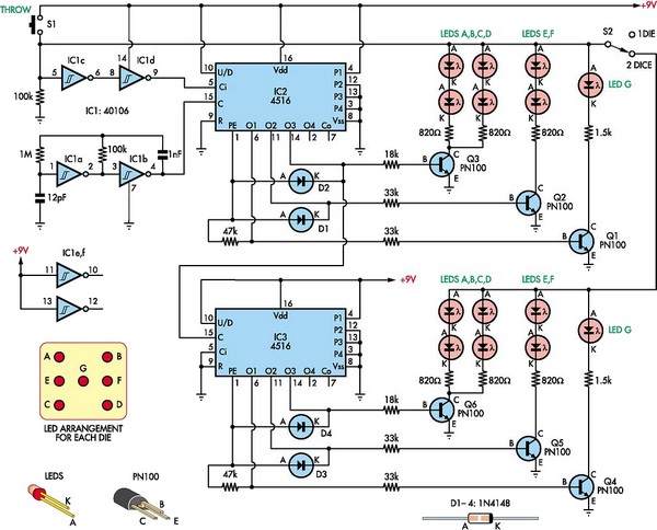
This circuit utilizes two 4516 integrated circuits (ICs) to simulate a game involving two dice. A switch is included to select whether one or two dice will be activated with each press. A 9-volt battery is sufficient for power...
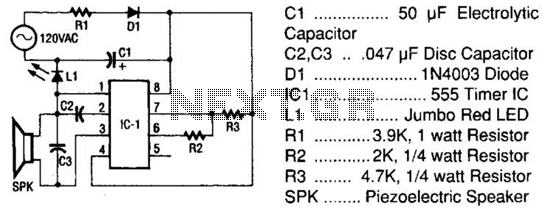
The tester comprises a rectifier circuit and a multivibrator circuit. The alternating current (AC) voltage is half-wave rectified by diode D1 and stored in capacitor C1. Resistor R1 is employed to limit the current through D1 to a safe...

Electronic FM Telephone Transmitter Schematic. The following schematic design illustrates a circuit diagram for an FM telephone transmitter built on a compact PC board layout. This small design allows it to be easily integrated within the housing of a...
Today, it is no longer necessary to use discrete components for constructing oscillators. Many manufacturers now offer ready-made voltage-controlled oscillator (VCO) integrated circuits (ICs) that require only a few external components to determine the frequency. An example of such...
The mixer circuit described features three line inputs and three microphone inputs. The microphone inputs are designed for low impedance dynamic microphones with a range of 200 to 1000 ohms. Alternatively, an electret condenser microphone (ECM) can be used,...