
Sine-square wave oscillators

This circuit is designed to generate both sine and square waveforms across a broad frequency range, making it suitable for various applications, including signal testing, audio synthesis, and waveform generation. The core of the circuit typically utilizes an operational amplifier (op-amp) configured for oscillation, along with passive components such as resistors and capacitors that dictate the frequency response.
The sine wave output can be achieved by employing a Wien bridge oscillator configuration, which uses a combination of resistors and capacitors to create a feedback loop that stabilizes the oscillation frequency. The tuning of the frequency is accomplished by adjusting a single resistor in the feedback path, allowing for fine control over the output frequency. This design ensures that the sine wave maintains a low distortion level, suitable for high-fidelity applications.
For the square wave output, the circuit may incorporate a Schmitt trigger or a comparator to convert the smooth sine wave into a sharp, digital square wave. The transition points of the square wave can be adjusted by modifying the reference voltage levels, which can also be influenced by the same resistor used for tuning the sine wave frequency.
The frequency range of operation, from below 20 Hz to above 20 kHz, is facilitated by the selection of appropriate components, ensuring that the circuit can function effectively across this entire spectrum. This versatility makes the circuit valuable in educational settings, laboratories, and various electronic applications where different waveform outputs are required.
In summary, the circuit's ability to generate both sine and square waves, along with its simple tuning mechanism through a single resistor, contributes to its practicality and ease of use in a wide range of electronic projects.This circuit will provide both a sine and square wave output for frequencies from below 20 Hz to above 20 kHz The frequency of oscillation is easily tuned by varying a single resistor.
Related Circuits
A CD4017 is configured as a senary counter, with an input clock frequency of 300 Hz. Diodes VD1 to VD9 and resistors R1 to R3 form three three-input OR gates, which can each receive two 50 Hz three-phase wave...
The receiver consists of multiple subassemblies, including an active antenna, an amplifier featuring regeneration control and band-switching circuitry, an AM detector, a power amplifier, and an output device such as an internal speaker, external speaker, or headphones. Additionally, it...
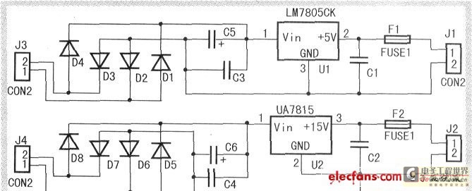
When the input voltage is between 198-242V, the average load current should be maintained at 0.5-1A, and the output voltage must remain at 15V with an error margin of less than 5%. The design and measurement of the stabilized...
This is a sine wave oscillator circuit, also known as an amplitude-stabilized sine-wave oscillator. It provides a high-purity sine wave output. This sine wave oscillator circuit is designed to generate a stable sine wave output with minimal distortion, making it...
Using only a single transistor and a few passive components, a fairly sensitive peak detector circuit can be built. This peak detector circuit is suitable for various applications. The peak detector circuit utilizes a single transistor, typically configured in a...
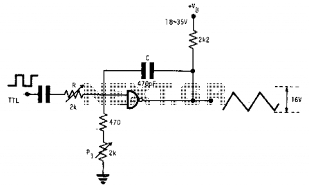
This fixed-frequency triangular waveform generator, driven by a TTL square wave, produces triangular waveforms with a peak-to-peak voltage of typically 16 V at frequencies reaching several MHz. The design utilizes a single AND open collector gate or an open...