
Square wave-to-triangle converter

The triangular waveform generator operates on a principle that combines digital and analog techniques to create a stable and precise output. The input TTL square wave serves as the timing reference, allowing the circuit to produce a triangular waveform at a fixed frequency determined by the timing components. The use of an open collector gate or inverter facilitates fast switching and integration, which is crucial for generating the desired waveform shape.
The integration process involves charging and discharging the capacitor through the resistor R, where the time constants are adjusted to achieve the correct slope of the triangular waveform. The gain provided by the open collector device enhances the output signal, ensuring that it reaches the desired amplitude. The adjustments of R and PI are critical, as they directly influence the frequency response and linearity of the output waveform.
The output characteristics are notably robust, as the amplitude and linearity remain stable across a range of supply voltages (VB). This flexibility allows the circuit to be utilized in various applications without significant recalibration, making it suitable for environments where voltage supply may vary.
In practice, when designing this circuit, careful attention must be paid to the choice of components, especially the capacitor value, which is crucial for maintaining the integrity of the waveform at higher frequencies. As the frequency increases, the capacitor's capacitance must be reduced to maintain the correct timing characteristics, ensuring that the triangular waveform remains sharp and well-defined.
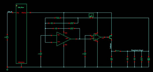
Overall, this fixed-frequency triangular waveform generator is an effective solution for applications requiring precise waveform generation, with the ability to adapt to different operating conditions while maintaining performance integrity.This fixed frequency triangular waveform generator driven by a TTL square wave generates typically 16-V p-p triangles at frequencies up to several MHz. It uses only one AND open collector gate, or one open collector inverter as a fast integrator with gain.
Careful successive adjustments of R and PI are needed. When correct adjustments are reached, output amplitude and linearity are largely independent of the value of VB, from a minimum of 18 V up to 35 V. The value of C shown is for 100 kHz; at higher frequencies, it must be reduced in proportion.
Related Circuits
The circuit illustrated in the schematic diagram below is an isolated DC-to-DC step-up converter. The term "isolated" indicates that there is no electrical connection between the input and output sections of the circuit. The isolated DC-to-DC step-up converter operates by...
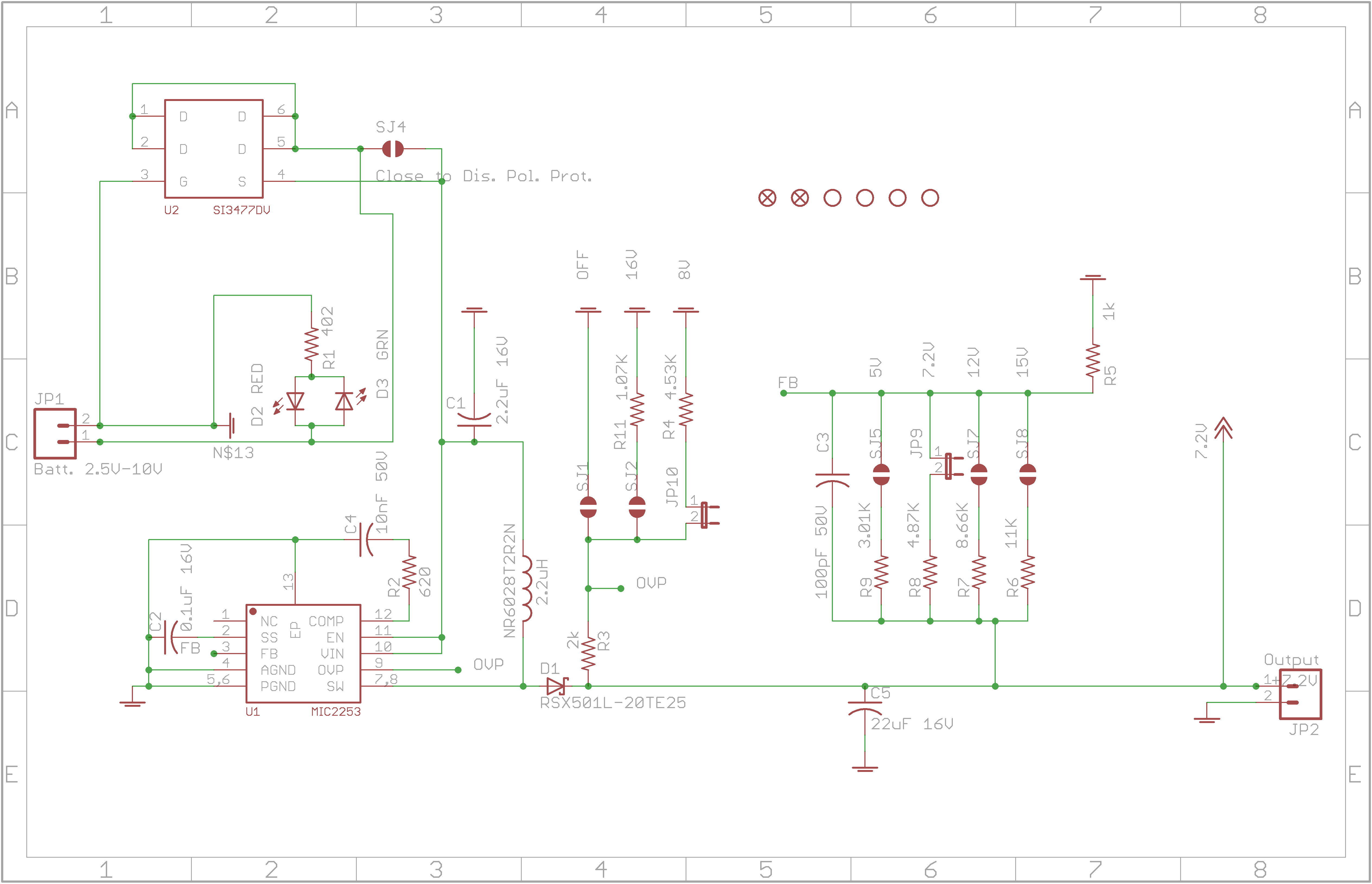
The circuit allows for various combinations of input voltages (Vin) and output voltages (Vout). The current case under debugging involves Vin=3.6V and Vout=7.2V, with a load represented by a 120-ohm resistor. The calculated duty cycle is D=0.5, indicating 50%,...
Connect with Cadence technologists and peers in the Cadence Community. Stay informed about technology trends, news, and opinions through blogs, forums, and social networking. The Cadence Community serves as a collaborative platform for professionals in the electronics design automation (EDA)...
A high voltage step-up DC power supply using adjustable flyback conversion. The circuit described is a high voltage step-up DC power supply utilizing an adjustable flyback converter topology. This design is particularly effective for applications requiring a significant increase in...
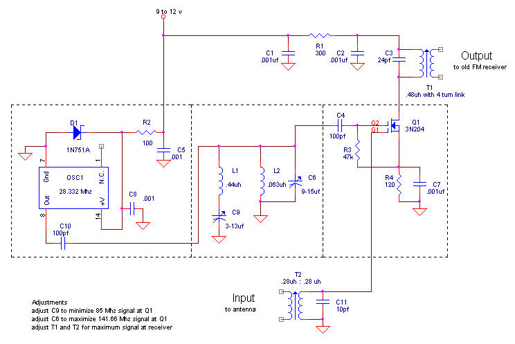
The FM broadcast band was relocated immediately after World War II from its original frequency just below 50 MHz to the current 88-108 MHz range. Hallicrafters was one of the companies that provided receiving converters for users of older...
The circuit diagram depicts a design that achieves 0.25% exponential conformity over a frequency range of 20 Hz to 15 kHz using a single LM392 and an LM3045 transistor array. The exponential function is generated by Q1, whose collector...