
Simple square wave generator

The described circuit is a basic square wave generator using two transistors, which highlights the functionality of positive and negative feedback in oscillator design. The primary components include two bipolar junction transistors (VT1 and VT2), resistors (R1, R2, R3, R4, R5), and a capacitor (C1). The configuration allows for the generation of a square wave output, where the pulse width and frequency can be adjusted through the selection of resistors and the capacitor value.
The circuit's operation begins with the application of voltage, initiating the conduction of VT1, which in turn biases VT2. This cascading effect creates a rapid switching action characterized by the avalanche effect, leading to a sharp rise and fall in voltage, producing a rectangular pulse. The feedback network consisting of R2 and C1 is crucial for maintaining oscillation, as it reinforces the conduction of both transistors during their on states.
The duty cycle, defined as the ratio of the pulse width to the total period of the waveform, is adjustable, allowing for versatility in applications. The output can be utilized in various circuits, including LED drivers for flashing lights, where the brightness can be fine-tuned by modifying the load and feedback resistors. This simplicity and effectiveness make the circuit an excellent choice for educational purposes and practical applications in electronic design.
Overall, this square wave generator serves as a fundamental example of oscillator design, illustrating key principles of transistor operation, feedback mechanisms, and the relationship between component values and circuit performance.Typically square wave generators are based on symmetrical multivibrator with bipolar transistors of the same structure and with two frequency determining network. However, you can construct more simple oscillator with two transistors of different structure (see figure 1) with only one frequency determining network.
The circuit works this way: when the supply voltage is applied (capacitor C1 is not charged) the transistor VT1 begins to conduct the current flowing through the bias resistor R1. Collector current of this transistor is the base current for the transistor VT2 and this collector current opens the transistor VT2.
The voltage at the collector load of the transistor VT2 increases through a network of C1R2, and this further opens the transistor VT1, and as a result there is an avalanche process of opening the two transistors - it`s forming the front of the rectangular pulse. The duration of the pulse is determined by charging the capacitor C1 through resistor R2. As the capacitor C1 is charging, the base current of the transistor VT1 is reduced, and there comes a time when there is starting an avalanche process of closing both transistors.
On the load is formed a falling pulse edge. The duration between pulses is determined by the duration of the discharge of the capacitor C1 by the current flowing through resistors R1 and R2. Then the process repeats. The work of the generator can be explained differently. Two-stage amplifier circuit has a positive feedback (network R2C1) and in the same time the amplifier is put in the linear mode of the transistor VT1 by applying bias on its base through resistor R1.
Therefore, the relaxation oscillations are generated. To stabilize the operation of the generator each cascade has a negative feedback - it is weak in the first stage (resistor R1), and in the second stage the emitter circuit of transistor VT2 has a resistor R5. The generator operates steady at a supply voltage in range from 1. 5 to 12 V, while the consumption current is in range from 0. 15 mA to some mA. The amplitude of the output pulses on the "Out 1" is a little more than half of the supply voltage, and at the "Out 2" it is about 10 times smaller.
If you want, you can add another stage of the voltage divider (1/100), by inserting the resistor of 24 Ohms between the lower terminal of the resistor R4 and the common wire. With the values of components, shown in fig. 1, and with the supply voltage of 2. 5 V the consumption current of the circuit is 0. 2 mA and the frequency is 1000 Hz, the duty-cycle is 50% (meander), the amplitude of the signal at the "Out 1" is 1V.
Of course, in such a simple generator the parameters of the signal is significantly depends on the power supply voltage. Therefore, the generator should be adjusted at the same voltage with which it will be used. In case of the absence of the generation, adjust the value of resistor R1 and, possibly, R5 (replace it by resistors with another value).
Duty cycle is set by selecting the value of the resistor R2. One possible application of this generator is a flashing light. Then the load (LED or incandescent lamp) is connected in series with the resistor R5, and use the capacitor C1 with capacity of 1 F to get the frequency of oscillation about 0. 5. 1 Hz. To obtain the necessary brightness of the light, the value of resistors R3, R5 can be reduced, and the resistor R4 can be eliminate as unnecessary.
🔗 External reference
Related Circuits
The circuit consists of a lag comparator with amplifier A1 and an inverting integrator A2. The charging and discharging time constant is determined by the integral resistors (R1 + RP1) and the capacitor C1. Diodes VD1 to VD5 form...
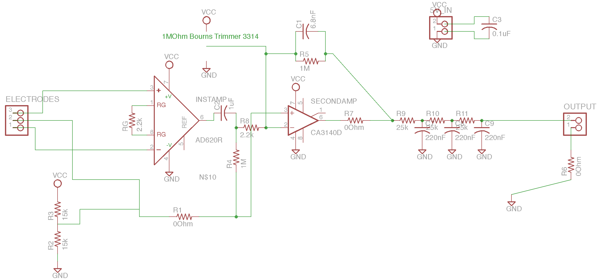
The circuit is based on the designs of Chipstein and Cornell, utilizing an instrumentation amplifier (AD620) to measure the voltage difference between two locations on the body. A second amplifier (CA3140) further amplifies this differential signal. A potentiometer is...
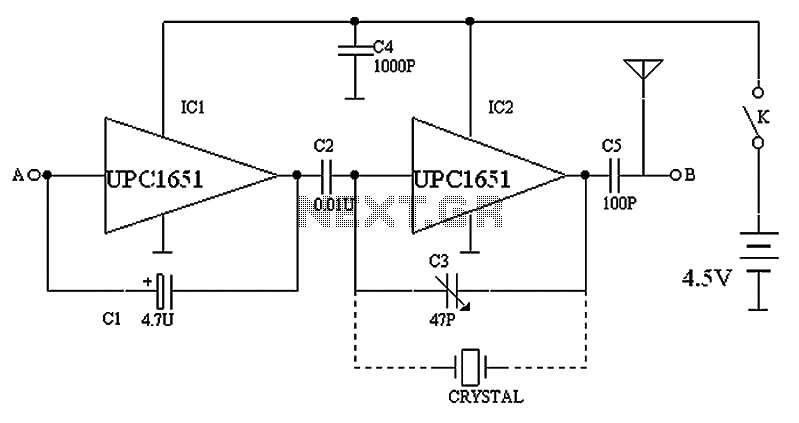
The circuit depicted in the figure includes IC1 and C1, which form a low-frequency oscillator operating at approximately 400 Hz. IC2 and C3 are configured to create a frequency oscillator around 37 MHz. The low-frequency signal is output from...
A Georgia Republic inventor, Tariel Kapanadze, claims to have invented a 5 kilowatt free energy generator. In a demonstration video, the device appears to produce copious amounts of energy from no visible source. More: The components apparently include a...
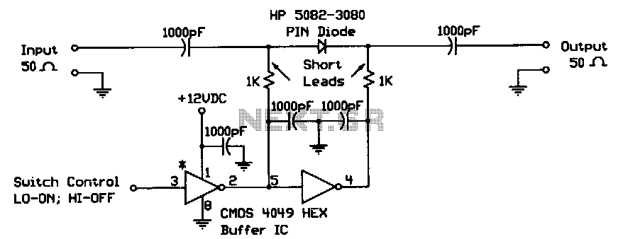
When the digital logic level at the control input is low, the PIN diode is forward-biased by the CMOS gates. The two 1-KΩ bias resistors limit this current to the PIN diode's safe forward current limit. In this state,...
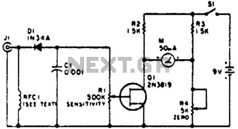
This circuit employs a FET as a DC amplifier within a bridge configuration. Resistor R4 is adjusted for meter nulling with switch J1 short-circuited. Any surplus 50-mA meter can be utilized in this circuit. RFC1 represents a suitable RF...