
Square wave generator III

The circuit operates by utilizing a stable RC oscillator configuration, which is essential for generating precise square waveforms necessary for testing television monitor amplifiers. The choice of NAND gates (IC4-4011) provides a reliable method of oscillation, with the RC time constant determining the frequency of oscillation. The use of bilateral switches (IC2, IC3-4016) allows for dynamic alteration of the capacitor value, thereby enabling the circuit to produce various frequencies as required for different testing conditions.
The counter/decoder (IC1-4017) plays a critical role in controlling the timing of the waveform generation. It receives clock pulses, which are generated from a stable clock source, and outputs signals that drive the bilateral switches. The synchronization of these outputs with vertical blanking pulses ensures that the waveform generation is coherent with the television signal, facilitating accurate characterization of the monitor's response.
Horizontal synchronization is achieved through the application of composite blanking pulses, which are negative in polarity. This technique ensures that the generated waveforms align with the horizontal synchronization requirements of the television system, thereby preventing any potential distortion during the testing phase.
The frequency steps provided by the oscillator (460 kHz to 3600 kHz) are crucial for evaluating the frequency response of television monitor amplifiers across a range of operational conditions. Each frequency corresponds to a specific test scenario, allowing engineers to assess the performance of the monitor at various signal frequencies.
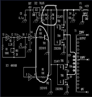
Finally, the mixer stage is essential for combining the generated video signal with the composite sync signal. This integration is vital for producing a composite video output that can be utilized for further testing or analysis, ensuring that the generated signals are compatible with standard television input requirements. Overall, this circuit serves as a valuable tool for engineers and technicians in the field of television technology, providing a versatile means of testing and characterizing monitor performance.The generator described here is intended for multiburst signal square waveform generation and can be used as a device for characterizing the response of TV monitor amplifiers as shown. The circuit is an RC oscillator with NAND gates (IC4-4011), with its capacitor C changed periodically by means of bilateral switches (IC2, IC3-4016).
The control inputs of bilateral switches are driven by the outputs of a counter/decoder (IC1-4017) the operation of which is determined by generated clock pulses, so that they occur eight times at half-picture (field). These pulses are locked to vertical blank pulses. Horizontal synchronization is achieved by means of composite blanking pulses (negative polarization) applied to pins 1 and 5 of IC4. The oscillator frequency changes in the following discrete steps: 460 kHz, 680 kHz, 900 kHz, 1400 kHz, 2700 kHz, 3600 kHz, for the time of one frame.
The video signal is fed on a mixer where it is superimposed with a composite sync signal.
Related Circuits
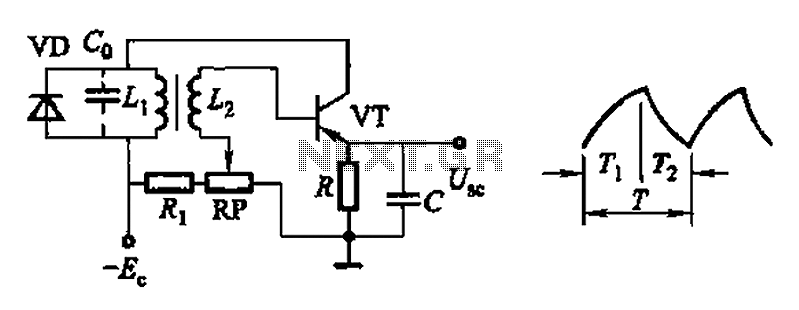
Common non-sinusoidal oscillator circuit, waveform and frequency formula - pulse wave oscillator - single-junction transistor blocking oscillator. The common non-sinusoidal oscillator circuit described is a pulse wave oscillator that utilizes a single-junction transistor in a blocking configuration. This type of...

This well-known circuit can be implemented using any rail-to-rail output comparator or the classic LMC555. The output period is defined by the equation 2log(2)RC = 1.386RC, exhibiting a stability of better than ±100 ppm/°C concerning temperature variations and ±100...
The JBL "Bass Wave" amplifier is a compact 100-watt amplifier featuring a built-in active filter that includes a single-pole high-pass filter at 10 Hz and a single-pole low-pass filter at 85 Hz. Priced at an affordable $50 USD, it...
The circuit includes 10K resistors at the bases of the transistors and 1K resistors at the collectors. It is essential to retain these components when relocating the transistors, as omitting the 10K resistors could result in transistor failure, and...
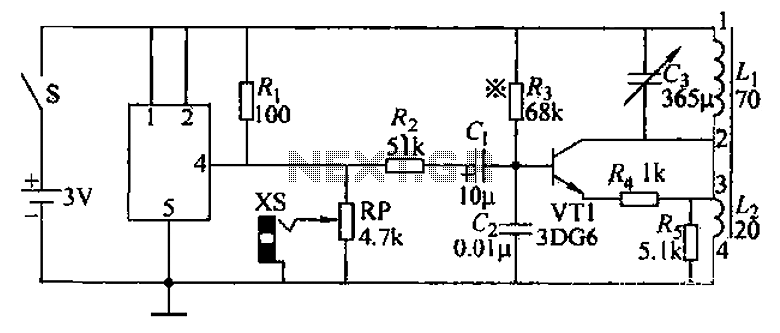
An audio frequency signal generator can output audio signals, 465 kHz spectral amplitude signals, and 52.5 Hz to 16 kHz high-frequency amplitude-modulated signals. The high-frequency oscillator's vibration frequency is determined by the components G and L. A variety of...
This application report presents a potential solution to the telecom plug-in power issue, utilizing a nominal 48 Vdc system bus and a module that requires two low-voltage supply outputs. It includes a comprehensive design methodology for customizing the circuit...