
sine wave generator with low distortion

The low-frequency harmonic signal generator is a critical tool designed to produce stable and precise low-frequency signals, which are crucial for testing and analyzing the performance of audio amplifiers and related electronic circuits. This device typically operates within a frequency range from a few hertz up to several kilohertz, allowing it to generate various harmonic signals such as sine, square, and triangle waves.
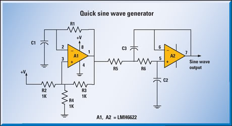
The circuit often comprises an oscillator, which is the core component responsible for generating the desired frequency output. Commonly used oscillator configurations include the Wien bridge oscillator or the phase-shift oscillator, both of which can produce low-frequency sine waves with high stability. For generating square and triangle waves, a Schmitt trigger or a relaxation oscillator circuit may be employed, providing sharp transitions and well-defined edges.
Additionally, the output stage of the signal generator typically includes an amplifier to ensure that the signal can drive various loads without distortion. This amplifier stage may utilize operational amplifiers configured for gain adjustment, allowing the user to control the amplitude of the output signal.
To enhance usability, the signal generator may incorporate features such as frequency and amplitude controls, output impedance matching, and waveform selection switches. These controls enable the user to tailor the output signal to meet specific testing requirements.
In terms of power supply, the circuit can be powered by a standard DC source, often with voltage regulation to maintain stable operation. Proper decoupling capacitors are also included to filter out noise and ensure clean signal generation.
Overall, the low-frequency harmonic signal generator serves as an indispensable instrument in the field of electronics, facilitating the thorough testing and evaluation of audio amplifiers and other related circuits.The following construction of low-frequency harmonic signal generator was necessary for debugging and measurement of audio amplifiers and other circuits,.. 🔗 External reference
Related Circuits
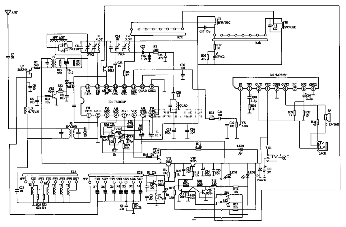
The circuit diagram for the Desheng 89701 type radio, a compact shortwave receiver, is provided below. The Desheng 89701 is designed for shortwave reception, making it suitable for capturing a variety of radio frequencies across the shortwave band. The circuit...
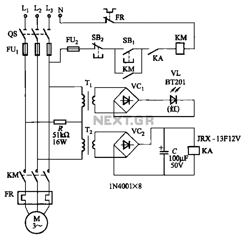
The circuit depicted in Figure 3-92 employs a dual-phase sequence protection relay for sensing. When the power supply exhibits a positive phase sequence (U, V, W), the relay KA is activated. If the power supply maintains the correct phase...
This Antenna is most widely used all over the world. For example, when you see a police car it has a transmitter with Ground Pole Antenna. The body of the car serves as ground. It accepts load from a...
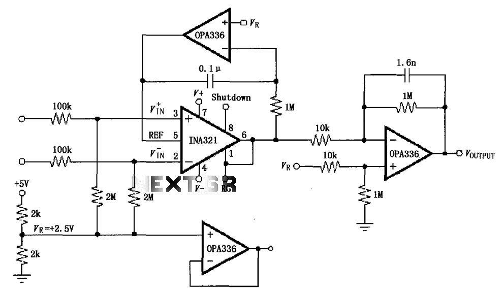
The INA321/322 forms a low-cost, medium-accuracy ECG amplifier circuit. The INA321 receives input signals from the patient's arm, amplifying them before sending the modified output to the operational amplifier OPA336. The OPA336 generates an output voltage from the inverting...
Rf = 100 k preset. The slider is positioned approximately a quarter of the way around. This component is utilized to control the gain, which should be minimized while ensuring the oscillator starts reliably. Zener diodes limit the oscillator...
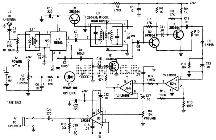
The integrated circuit Ul (an NE602 double-balanced mixer) functions as both an oscillator and a frequency mixer. Signals from the antenna input (at Jl) are transmitted through a DC-blocking capacitor C1 to the RF gain control, Rl, and subsequently...