
Desheng 89701 type radio small shortwave Wang schematic

The Desheng 89701 is designed for shortwave reception, making it suitable for capturing a variety of radio frequencies across the shortwave band. The circuit typically includes several key components that ensure optimal performance and functionality.
At the core of the radio's operation is the RF (radio frequency) front-end, which consists of an antenna, RF amplifier, and a mixer. The antenna captures radio signals, which are then amplified by the RF amplifier to enhance the signal strength. The mixer combines the amplified RF signal with a local oscillator signal to produce an intermediate frequency (IF) signal, which is easier to process.
The IF stage usually includes additional amplification and filtering components to improve signal clarity and reduce noise. This stage is crucial for isolating the desired signal from unwanted frequencies. The filtered IF signal is then demodulated to recover the audio information, which can be done using either amplitude modulation (AM) or single sideband (SSB) techniques, depending on the design specifications of the radio.
The audio output stage follows the demodulation process, where the audio signal is amplified and sent to a speaker or headphone output. Volume control and tone adjustment features may also be included to enhance user experience.
Power supply considerations are critical in the design of the Desheng 89701. It typically operates from batteries or an external power source, requiring voltage regulation and filtering to ensure stable operation.
Overall, the Desheng 89701 circuit diagram illustrates a well-structured shortwave radio design that balances performance, size, and user functionality, making it a practical choice for shortwave enthusiasts.Desheng 89701 type radio (small shortwave Wang) circuit diagram is shown below:
Related Circuits
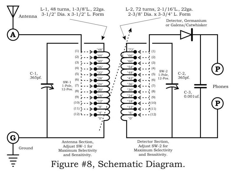
A two-circuit tuner, similar to a loose coupler, is an effective method for achieving selectivity without compromising sensitivity. The circuit introduces the signal to the primary antenna section via the SW-1 arrangement, allowing the antenna to be matched to...
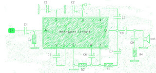
The amplifier circuit is well-suited for use in subwoofer speakers due to its robust performance. This circuit utilizes an integrated circuit (IC) based on the STK series. It can be employed in vehicles equipped with speakers or a subwoofer...
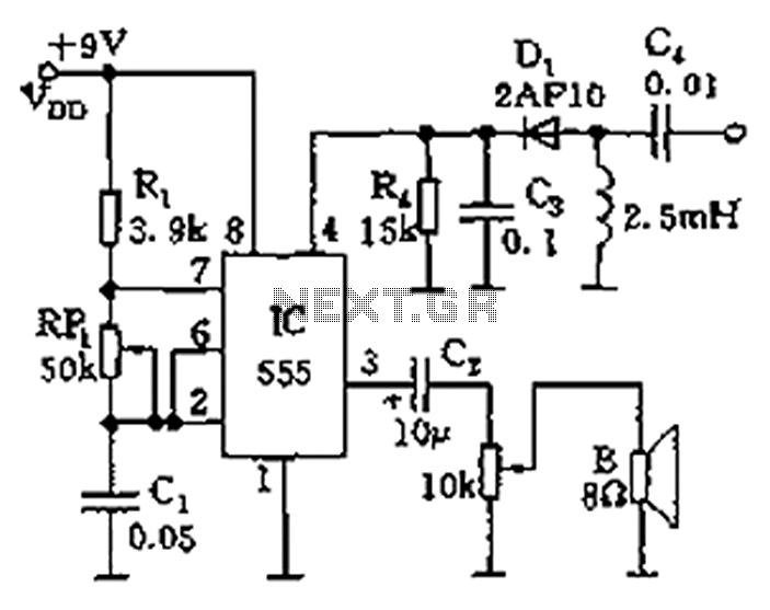
The circuit features a 555 timer integrated circuit along with components R1, RP1, C1, and others, which together form an audio oscillator. The frequency of the oscillator is determined by the formula f = 1.44 / ((R1 + 2...
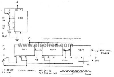
This circuit is designed to provide long time delays using the integrated circuit Timer 555. It utilizes the NE555 to generate pulse frequencies, which are then divided by a 4017 decade counter to achieve the desired delay. The component...
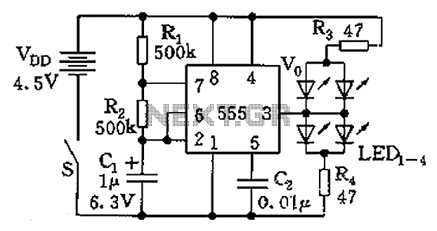
The circuit consists of a 555 timer and a light-emitting diode (LED) array. The 555 timer, along with resistors R1, R2, and capacitor C1, forms an astable multivibrator configuration. The oscillation frequency is calculated using the formula f =...
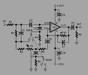
To achieve optimal audio reproduction at various listening levels, it is essential to incorporate tone-setting controls that align with the well-documented characteristics of human auditory perception. Specifically, human ear sensitivity exhibits a non-linear response across the audible frequency spectrum,...