
Sine Wave To Square Wave Converter Circuit

The circuit utilizes a 2-input NAND Schmitt trigger, which is an essential component for signal shaping and noise immunity. The Schmitt trigger is characterized by its hysteresis, meaning it has two distinct threshold voltages: one for transitioning from low to high and another for transitioning from high to low. This feature helps eliminate any noise that may be present in the input sine wave, ensuring a clean square wave output.
In this configuration, the sine wave input is fed into one of the inputs of the NAND gate. The second input is tied to a logic high (Vcc), effectively transforming the NAND gate into a NOT gate. The adjustable trigger level allows for fine-tuning of the input voltage at which the output state changes. When the input sine wave exceeds the upper threshold voltage, the output of the NAND gate switches from high to low, creating a square wave that toggles between these two states.
The output frequency of the square wave is determined by the frequency of the input sine wave. The circuit can be used in various applications, such as signal conditioning, waveform generation, and in digital systems where a square wave is required for clock signals or other timing applications. Proper design considerations, including power supply decoupling and input/output impedance matching, should be taken into account to ensure optimal performance of the circuit. This circuit turns a sine wave into a square wave. It is comprised of a single 2-input NAND Schmitt trigger that`s configured as an inverter with a trigger level adjustment at its input. As the input voltage rises above the gate`s trigger point, the output snaps to its alternate state, producing a square-wave output.
Related Circuits
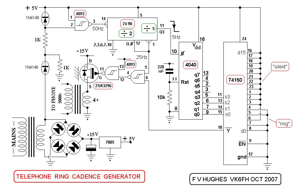
This design aims to restore the classic style of telephones that utilized a pair of gongs to signal an incoming call, evoking a sense of nostalgia with the familiar sound of ringing bells. Presented here is a "Telephone Ring...
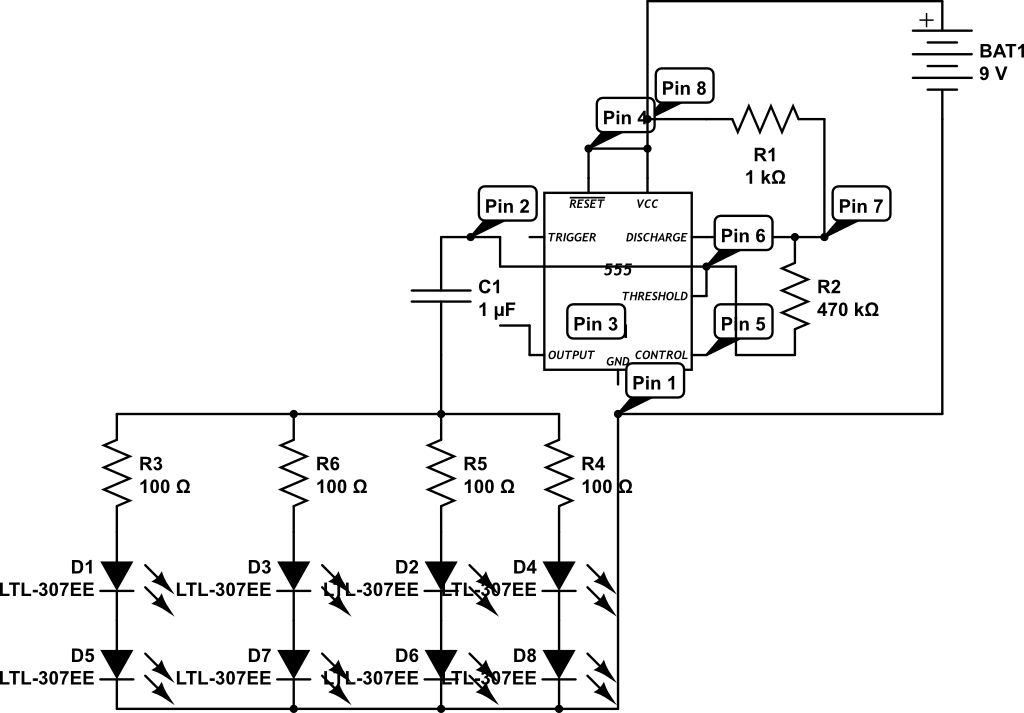
LEDs are rated for a continuous current of only 30 mA, while this circuit operates them at approximately 50 mA. Although this is acceptable for low duty cycles with short pulses, the intended design has a high duty cycle....
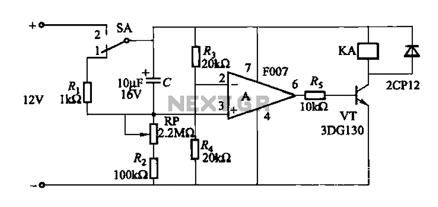
A delay circuit utilizing an operational amplifier functions as a comparator, providing high timing accuracy. The timer's delay range is from 1 to 30 seconds. The delay time is determined by resistors Ri, RP, and capacitor C. By adjusting...
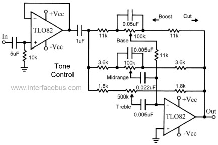
This topic continues the coverage of audio tone controls. The first entry started with a passive tone control circuit using different RC filter configurations and introduced an active filter. The second entry showed a fully designed 2-band active tone...

This inverter circuit is designed to power electric razors, stroboscopes, flash tubes, and small fluorescent lamps using a 12-volt car battery. Unlike conventional feedback oscillator inverters, this design features a separate oscillator from the output stage, allowing for easy...
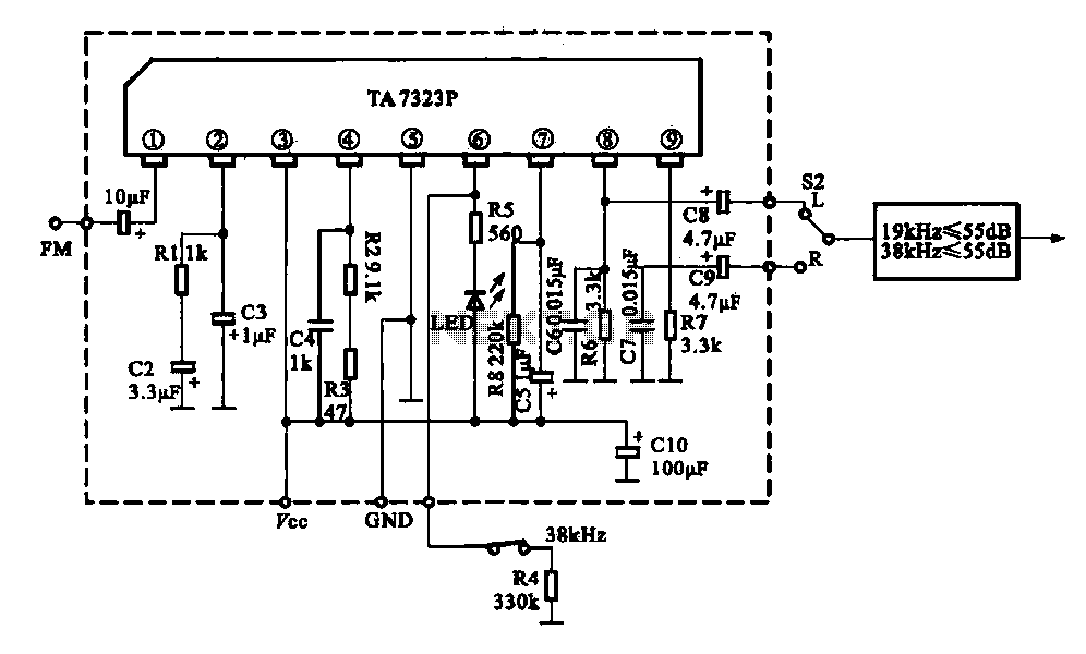
The current design utilizes a stereo decoder integrated circuit (IC) that guarantees a channel separation of 45 dB or more due to its manufacturing process. The intermediate frequency amplifier gain is sufficiently high to achieve a channel separation greater...