
emergency light circuit diagram

The mains supply of 230V AC is stepped down to 18V AC (RMS) using a 230V AC primary to 0-18V AC, 2A secondary transformer (X1), generally used in 36cm B&W TVs. Diodes D1 through D4 form bridge rectifier and capacitor C5 filters the voltage, providing about 25V DC at the output.
Charging section includes 33-ohm, 10-watt resistor R2 which limits the charging current to about 425 mA when battery voltage is about 10. 2V, or to 325 mA when battery voltage is about 13. 5V. When the battery charges to 13. 5V (as set by VR2), zener diode D17 goes into breakdown region, thereby triggering triac TR1. Now, since DC is passing through the triac, it remains continuously on even if the gate current is reduced to zero (by disconnecting the gate terminal).
Once the battery is fully charged, charging section is cut-off from the battery due to energisation of relay RL2. This relay remains on even if the power fails because of connection to the battery via diode D10. S4, a normally closed switch, is included to manually restart the charging process if required. Battery disconnect and charging restart section comprises an NE555 timer (IC2) wired in monostable mode.
When the battery voltage is above 10. 2V (as indicated by red LED D15), zener diode (D16) remains in the breakdown region, making the trigger pin 2 of IC2 high, thereby maintaining output pin 3 in low voltage state. Thus, relay RL3 is on and relay RL4 is off. But as soon as the battery voltage falls to about 10. 2V (as set by preset VR1), zener diode D16 comes out of conduction, making pin 2 low and pin 3 high to turn on relay RL4 and orange LED D13.
This also switches off relay RL3 and LED D15. Now, if the mains is available, charging restarts due to de-energisation of relay RL2 because when relay RL4 is on, it breaks the circuit of relay RL2 and triac TR1. But if the mains supply is not present, both relays RL3 and RL1 de-energise, disconnecting the battery from the remaining circuit.
Thus when battery voltage falls to 10. 2 volts, its further discharge is eliminated. But as soon as the mains supply resumes, it energises relay RL1, thereby connecting the battery again to the circuit. Light sensor section also makes use of a 555 timer IC in the monostable mode. As long as normal light is falling on LDR1, its resistance is comparatively low. As a result pin 2 of IC3 is held near Vcc and its output at pin 3 is at low level. In darkness, LDR resistance is very high, which causes pin 2 of IC3 to fall to near ground potential and thus trigger it.
As a consequence, output pin 3 goes high during the monostable pulse period, forward biasing transistor T3 which goes into saturation, energising relay RL5. With auto/bypass switch S2 off (in auto mode), the load gets connected to supply via switch S3. If desired, the load may be switched during the day-time by flipping switch S2 to on position (manual).
Preset VR3 is the sensitivity control used for setting threshold light level at which the load is to be automatically switched on/off. Capacitors with the relays ensure that there is no chattering of the relays. When the mains is present, diode D8 couples the input voltage to regulator IC1 whereas diode D10 feeds the input voltage to it (from battery) in absense of mains supply.
Diode D5 connects the load to the power supply section via resistor R5 when mains is available (diode D18 does not conduct). However, when mains power fails, the situation reverses and diode D18 conducts while diode D5 does not conduct.
. The load can be any bulb of 12 volts with a maximum current rating of 2 amperes (24 watts). Resistor R5 is supposed to drop approximately 12 volts when the load current flows through it during mains availability. Hence power dissipated in it would almost be equal to the load power. It is therefore desirable to replace R5 with a bulb of similar voltage and wattage as the load so that during mains availability we have more (double) light than when the load is fed from the battery.
For setting presets VR1 and VR2, just take out (desolder one end) diodes D7, D10 and D18. Connect a variable source of power supply in place of battery. Set preset VR1 so that battery-high LED D15 is just off at 10. 2V of the variable source. Increase the potential of the variable source and observe the shift from LO BAT LED D13 to D15. Now make the voltage of the source 13. 5V and set preset VR2 so that relay RL2 just energises. Then decrease the voltage slowly and observe that relay RL2 does not de-energise above 10. 2V. At 10. 2V, LED D15 should be off and relay RL2 should de-energise while LED D13 should light up. Preset VR3 can be adjusted during evening hours so that the load is on during the desired light conditions Disclaimer: All the information present on this site are for personal use only. No commercial use is permitted without the prior permission from authors of this website. All content on this site is provided as is and without any guarantee on any kind, implied or otherwise.
We cannot be held responsible for any errors, omissions, or damages arising out of use of information available on this web site. The content in this site may contain COPYRIGHTED information and should not be reproduced in any way without prior permission from the authors.
🔗 External reference
Related Circuits
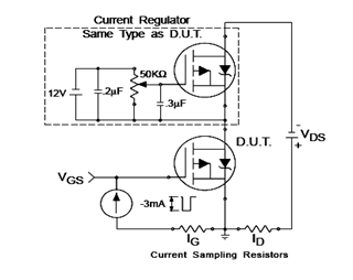
The IRF9540N Gate Charge Test Circuit is illustrated in the diagram below. The IRF9540N is recognized as a rectifier device that employs advanced processing techniques to attain an exceptionally low on-resistance per unit area, as stated in the datasheet....
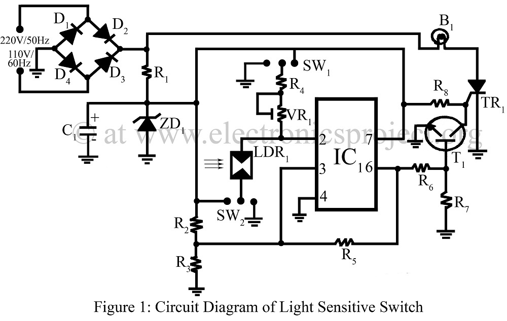
A light-sensitive switch, also known as a dark-sensitive switch, is a specialized switch that utilizes an operational amplifier integrated circuit (IC) LM74 in conjunction with a light-dependent resistor (LDR). The light-sensitive switch circuit operates by detecting ambient light levels...
The microphone preamplifier circuit design presented in this schematic utilizes the SSM2015 produced by Precision Monolithics Inc. (PMI), which offers high amplification. The SSM2015 is a low-noise, low-distortion integrated circuit designed specifically for microphone preamplification. It features a differential input...
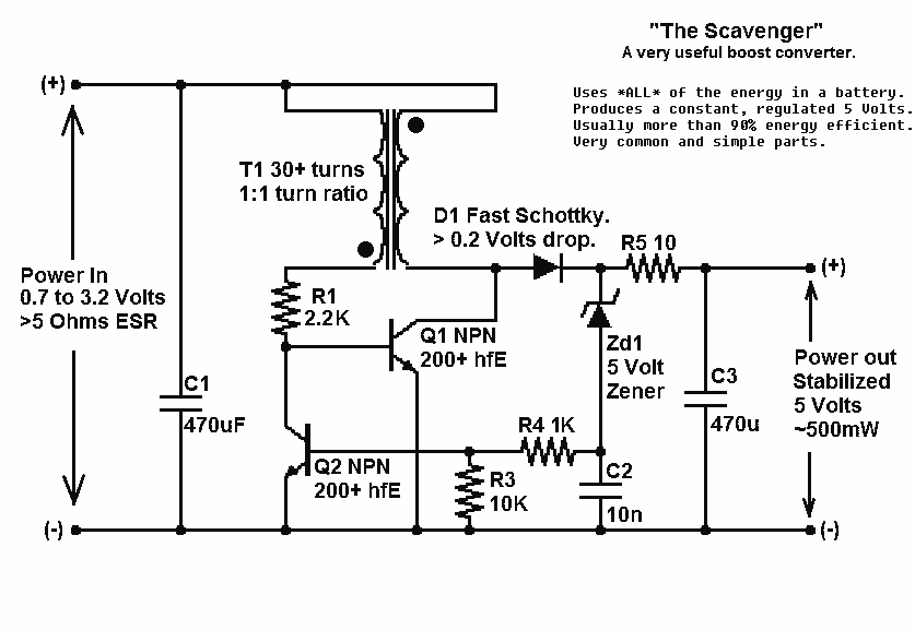
Presented here is a significant advancement in the design of simple, cost-effective, and efficient boost converters. To achieve an effective design, it is essential to convert current to voltage as efficiently as possible. This circuit excels in this regard. The...
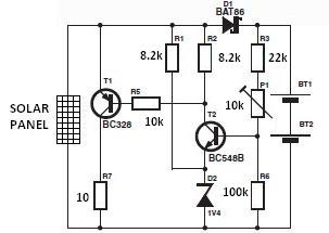
The nominal voltage of the solar charger circuit module is determined by the number of battery cells to be charged. Due to the typical voltage drop of 0.3 to 0.4 V across Schottky diode D1, the nominal voltage should...
This continuous wave (CW) transmitter is capable of producing an output power of up to 3 watts. By applying a 24-volt supply to transistor Q2, the output power can be increased to as much as 10 watts. It is...