
Power supply protection circuit

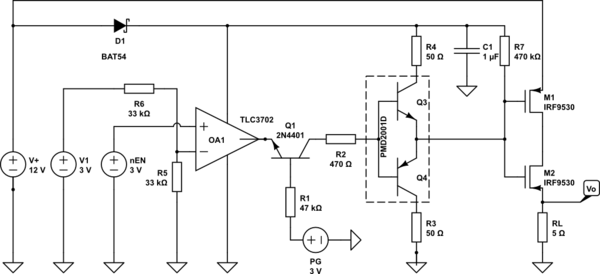
In this circuit, the primary function is to ensure the protection of sensitive equipment from overvoltage conditions. The design includes a voltage regulator that steps down the input voltage from 12 V to a stable 5 V. The trip mechanism is critical; it is configured to activate at 5.7 V, slightly above the desired output voltage, providing a buffer to prevent damage to the load.
The voltage divider formed by the 330-ohm resistor and the 500-ohm potentiometer is essential for monitoring the output voltage. The adjustable potentiometer allows for fine-tuning of the voltage divider ratio, enabling precise voltage sampling. The output voltage is continuously monitored, and if it surpasses the trip voltage, the SCR becomes conductive, effectively shorting the fuse and causing it to blow. This action interrupts the circuit and protects the downstream components.
The 2N2906 transistor is utilized as a switch that is normally off, controlled by the SCR and the 10 kΩ resistor. The LED indicator serves as a visual alert, illuminating when the output voltage exceeds the safe threshold. The 2N3906 transistor acts as an additional control element, receiving base current when the SCR conducts, ensuring that the LED lights up to signal an overvoltage condition.
Overall, this circuit design exemplifies a robust approach to voltage regulation and overvoltage protection, combining passive and active components to create a reliable safeguard for electronic equipment.When using a regulated supply to reduce a supply voltage there is always the danger of component failure in the supply and consequent damage to the equipment. A fuse will protect when excess current is drawn, but might be too slow to cope with overvoltage conditions.
The values shown are for a 12 V supply being dropped to 5 V. The trip voltage is set to 5.7 V to protect the equipment in the event of a regulator fault. The 330 ohm resistor and the 500 ohm potentiometer form a potential divider which samples the output voltage as set by adjustment of the potentiometer. The SCR is selected to carry at least twice the fuse rating. The full supply voltage is connected to the input of the regulator. The 2N2906 is held bias off by the 10 k resistor and the SCR so that the LED is held off. If the output voltage rises above a set trip value then the SCR will conduct, the fuse will blow, and the 2N3906 will be supplied with base current via the 10 k resistor, and the LED will light up.
Related Circuits

Although the integrated circuit (IC) has largely replaced this circuit, the flexibility of the discrete device design still makes it practical. The components are readily available and cannot easily be eliminated. If desired, a small piece of metal can...

A CMOS logic gate is utilized in this circuit. When an object approaches the antenna, the change in oscillator output is detected by components 1)1 and 1)2, which is then amplified by U1C. This amplification drives Q1, activating alarm...
A battery switch-over circuit is being developed, consisting of two parallel lanes as depicted in the circuit diagram. The operational voltage range spans from 3V to 12V. Only one lane should be active at any given time, which is...
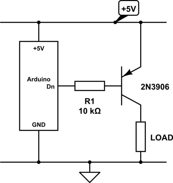
The emitter will consistently be a few hundred millivolts lower than the base voltage in this configuration. With the base voltage set at 5V, the emitter voltage is likely to be around 4.5V, depending on the current drawn by...
Many sites do not provide circuits for driving these transformers; they simply state that they are ineffective. However, this assertion is contested. A circuit has been developed that operates effectively, with significant effort invested in determining the resonant frequency...
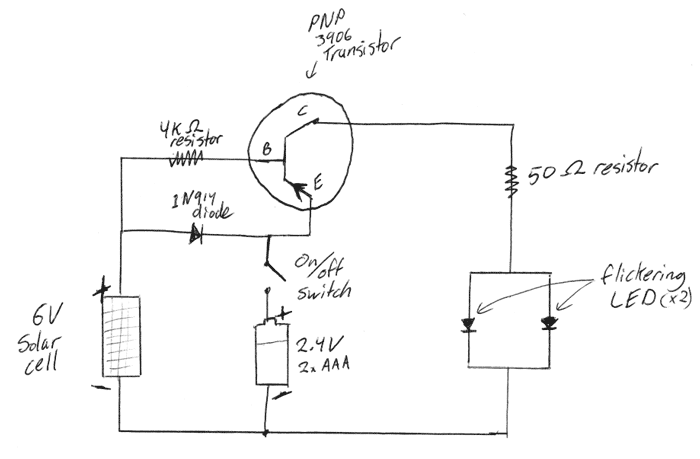
This is a DIY electronics project designed to enhance circuit design and building techniques. Copper lanterns were purchased and fitted with a circuit similar to outdoor solar lights. The circuit design is adapted from a simple design found on...