
Single-setpoint temperatre controller

The AD590 is a precision temperature sensor that outputs a current proportional to the absolute temperature. This current can be converted to a voltage using a resistor, R, which is connected in series with the sensor. The relationship between the current output and the voltage across R is given by Ohm's law, where the voltage drop (V) across R is equal to the current (I) multiplied by the resistance (R).
In this configuration, capacitor C is included to filter out any high-frequency noise that may affect the accuracy of the temperature readings. The value of R is crucial, as it determines the sensitivity and range of the voltage output. A standard value of 1 kΩ is often used, as it provides a suitable balance between voltage output and power dissipation.
To calibrate the output voltage to a specific temperature scale, resistor R2 is introduced. This resistor allows for the adjustment of the zero-scale voltage (Vzero). For the Celsius scale, setting R to 1 kΩ yields a Vzero of 0.73 volts, aligning the output with the Celsius temperature readings. Conversely, for the Fahrenheit scale, maintaining R at 1 kΩ adjusts Vzero to 0.60 volts, ensuring accurate temperature representation in Fahrenheit.
This configuration is commonly utilized in various applications, including temperature monitoring systems, HVAC controls, and industrial process automation, where precise temperature measurement is essential.The AD590 produces a temperature-dependent voltage across R (C is for filtering noise). Setting R2 produces a scale-zero voltage. For the Celsius scale, make R = 1 K and Vzero = 073 volts For Fahrenheit, R = 1 K and Vzero = 060 volts.
Related Circuits
Connect a 12-volt, 20-watt lamp and a 12-volt battery to the circuit, ensuring correct battery polarity. Momentarily pressing and releasing the button will turn the lamp on. Repeatedly pressing the button will cycle through different power levels. Pressing and...

This document details a dual-axis stepper motor controller design and printed circuit board for an equatorial mount. Acknowledgment is given to Bill Prewitt for his assistance in creating this webpage. An encapsulated PostScript file containing the artwork for both...
The circuit is built around two 555 timer ICs, U1 and U2. U1 is configured as a variable duty cycle oscillator with a constant time period of approximately 0.1 seconds. The duty cycle can be adjusted from 0 to...
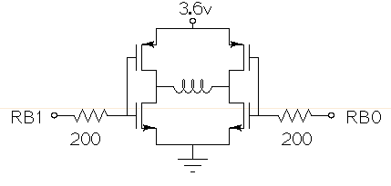
Drive a small (3.6V, <1A) brushed motor bidirectionally with a PIC microcontroller (MCU). The available space is extremely limited, so a single 3.6V power supply will be used for both the motor and the PIC, with minimal drive circuitry required. There is no dedicated motor driver IC that operates at this low voltage, making a discrete H-bridge the most suitable drive arrangement. The NXP PMV30UN and PMV32UP have been identified as suitable N-type and P-type drive MOSFETs. Since both the PIC and the motor share the same power supply, it is questioned whether it is possible to eliminate the usual driving circuitry for an H-bridge and connect the transistors directly to the MCU pins. Potential pitfalls of this approach should also be considered. To design a bidirectional motor drive circuit using a PIC microcontroller and a discrete H-bridge configuration, the following considerations must be taken into account. The H-bridge consists of four MOSFETs arranged in a configuration that allows current to flow through the motor in either direction, enabling bidirectional control. The NXP PMV30UN and PMV32UP MOSFETs are suitable candidates due to their low on-resistance and capability to operate at the required 3.6V supply voltage. The connections between the PIC MCU and the MOSFETs should be made with consideration of the gate drive requirements. Directly connecting the MOSFET gates to the MCU pins can be feasible, but it is essential to ensure that the MCU can provide sufficient gate drive voltage to fully turn on the MOSFETs. A typical threshold voltage for these MOSFETs is around 1V, so the output high level from the PIC should exceed this threshold to ensure efficient operation. It is also critical to incorporate pull-down resistors on the gate pins to prevent the MOSFETs from floating when the MCU is in a high-impedance state. This will help avoid unintended motor activation. Additionally, using gate resistors can help dampen any oscillations and limit inrush current during switching, which could potentially damage the MOSFETs or the MCU. Another consideration is the back EMF generated by the motor when it is switched off or when changing direction. This can induce voltage spikes that may damage the MCU or the MOSFETs. To mitigate this risk, flyback diodes should be placed in parallel with each MOSFET to provide a path for the back EMF, ensuring safe operation of the circuit. Thermal management is also a critical aspect of the design. Although the MOSFETs are rated for low on-resistance, continuous operation near their current limits can lead to significant heat generation. Adequate heat dissipation measures, such as heat sinks or thermal pads, should be considered. In summary, while it is possible to connect the MOSFETs directly to the MCU pins, careful attention must be given to gate drive requirements, protection against back EMF, and thermal management to ensure reliable and efficient operation of the bidirectional motor drive circuit.
This circuit is constructed using standard components and can be easily adapted for computer control. By utilizing inexpensive surplus transistors and a stepper motor, the overall cost of the circuit can be maintained at under $10. The described circuit is a...
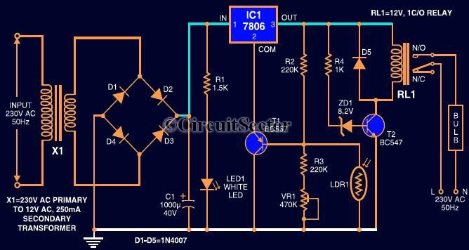
This circuit automates the control of street or porch lights. The automatic lamp controller circuit utilizes a 7806 voltage regulator IC, which can be employed to automate street lights, tube lights, or any other home electrical lighting systems. The...