
single phase half wave thyristor

In the Single Phase Half-Wave Rectifier circuit employing a thyristor, the operation is fundamentally different from traditional diode-based rectifiers. The SCR allows for controlled rectification, which is advantageous in various applications, such as motor control and power regulation. The firing angle (α) is a critical parameter, as it determines the point in the AC cycle at which the SCR begins to conduct. This angle is adjustable via the potentiometer, enabling fine-tuning of the output voltage and current characteristics.
The circuit typically consists of an AC power source, a thyristor, a load resistor, and a firing circuit. The firing circuit may include a resistor-capacitor (RC) timing network or other triggering mechanisms to create the required delay angle. When the AC voltage rises and reaches the threshold defined by the firing angle, the gate terminal of the SCR receives a triggering pulse, turning the thyristor on and allowing current to flow through the load.
During the positive half cycle of the AC input, as the SCR is triggered, the voltage across the load resistor increases, following the input waveform but only after the specified delay. This results in a clipped output waveform, where the initial portion of the half cycle is absent from the load. In the negative half cycle, the SCR remains off, preventing current flow and resulting in zero voltage across the load resistor during this phase.
The graphical representation of the output voltage clearly illustrates the relationship between the firing angle and the load voltage. The area under the curve during conduction represents the power delivered to the load, which can be adjusted by varying the firing angle. This characteristic makes the thyristor-based half-wave rectifier an effective solution for applications requiring variable control of power delivery.
Overall, the Single Phase Half-Wave Rectifier using a thyristor exemplifies the principles of controlled rectification in power electronics, showcasing the importance of firing angle control in managing output characteristics.In some of my previous posts, we have seen the simulations of half wave and full wave rectifiers using simple diodes. Now in this post, I would like to move on to power electronics domain with the first post being Single Phase half wave rectifier using thyristor .
In a thyristor or a so called SCR (Silicon controlled rectifier) circuit, the thyr istor is turned on after a delay angle alpha ( ±) using a firing circuit. ± is also called firing angle. So, in the circuit shown below, the SCR starts conducting only after a delay angle of ±, which is controlled by the potentiometer across the Anode and Gate terminals of the SCR. When the SCR starts conduction, the voltage appears across the load resistor of 1k © as shown in graph-2, otherwise during off condition of SCR, the voltage appears only across the SCR as shown in graph-3.
You can see the in the above graph that the voltage appears across the load only after a certain delay angle (firing angle). Conduction occurs only in positive half cycles, since during negative half cycles, the SCR is switched off.
Part of the sinusoidal waveform which do not appear across the load resistor appears across the thyristor as shown in the graph-3. These waveforms appear when the thyristor is on OFF mode 🔗 External reference
Related Circuits
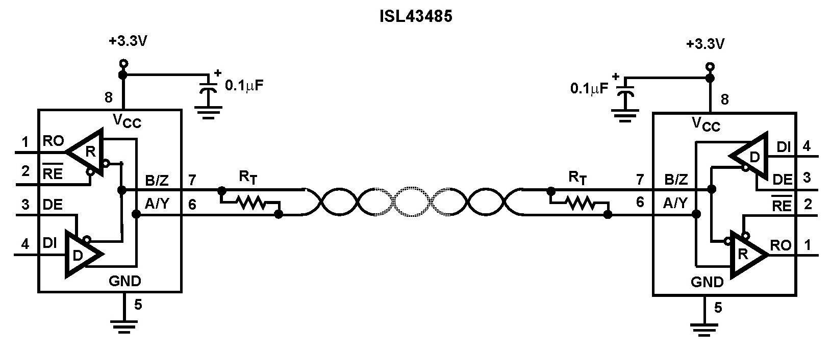
The Intersil ISL43485 is a high-speed BiCMOS transceiver powered by 3.3V, designed to comply with both RS-485 and RS-422 standards for balanced communication. This transceiver is specified for power supply tolerances of 10%, ranging from 3V to 3.6V. The...
The two circuits below illustrate generating low frequency sinewaves by shifting the phase of the signal through an RC network so that oscillation occurs where the total phase shift is 360 degrees. The transistor circuit on the right produces...
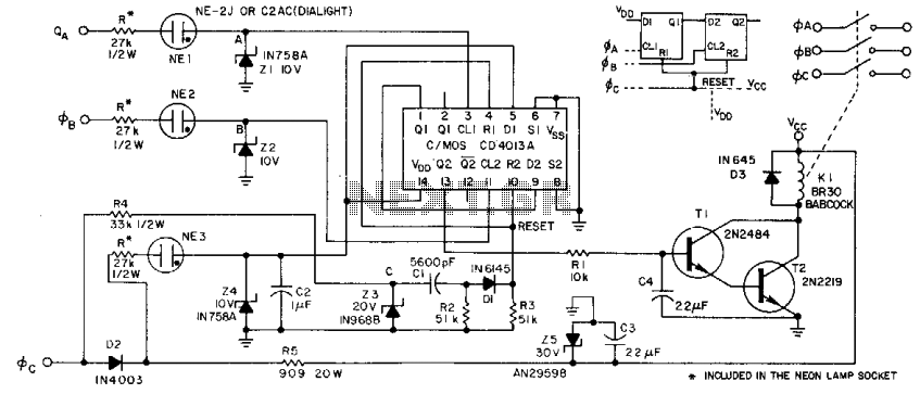
This circuit derives its supply voltage, Vcc, and Vdd from the AC supply. This factor, along with the neon lamps and zener diodes in the phase inputs, establishes a 50% threshold that detects low voltage or the absence of...

Schematic diagram for a dual polarity single channel input voltage to oscillating frequency control. The circuit can be divided into five parts. The reference voltage is established using a TL431 and a 1.2k resistor, functioning as a 2.5V regulator....
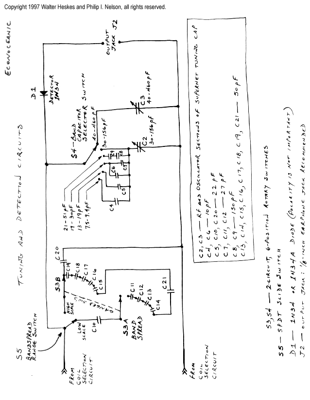
This project merges two significant themes from radio history: crystal radios and shortwave (SW) listening. It has been developed from the ground up by non-resident engineer Walter Heskes. Despite advancements in modern electronics, numerous crystal sets are actively used...

A center-tap 50Hz step-down transformer with two diodes is utilized to generate a series of positive sine pulses at 100Hz, which is applied to the base of Q6 through resistor R51. The 2N2646 is a unijunction transistor (UJT) housed...