
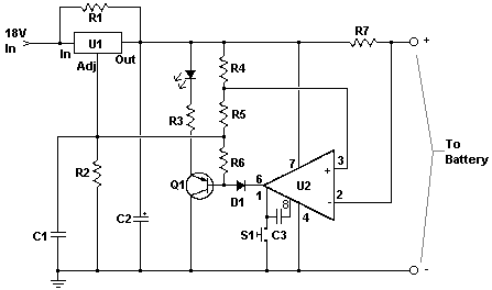
Single cell charger

The described circuit is designed to monitor the charging state of a battery and to transition between a high current charging mode and a low current float mode to maintain battery health and longevity. The 555 timer integrated circuit serves as the core component for timing and control functions.
In the charging phase, the circuit allows a current of 240 mA to flow into the battery. This is achieved by configuring the 555 timer in monostable or astable mode, depending on the desired timing characteristics. The output of the timer can control a transistor or a relay that connects the power supply to the battery.
Once the battery reaches a pre-set voltage level, indicating a full charge, the 555 timer detects this state through a voltage divider network connected to the battery terminals. Upon detection of the full charge, the timer output switches state, reducing the current to a float level of 12 mA. This transition is critical as it prevents overcharging, which can lead to battery damage or reduced lifespan.
The float state is maintained by adjusting the duty cycle of the 555 timer, ensuring that the battery remains topped off without excessive current flow. The circuit may also include additional components such as diodes for reverse polarity protection and capacitors for smoothing voltage fluctuations.
Overall, this circuit effectively manages battery charging by utilizing the 555 timer's versatile timing capabilities, ensuring both efficient charging and safe maintenance of the battery's state of charge.This circuit detects a full-charge state and automatically switches to a float condition—from 240 mA to 12 mA. The circuit uses the 555 timer.
Related Circuits
This charger is designed to quickly and efficiently charge most lead-acid batteries. It is an electronics project that is easy to construct, and a circuit diagram is included. The lead-acid battery charger circuit typically consists of several key components that...
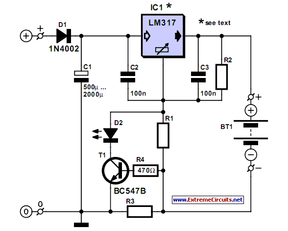
A simple NiCd charger can be constructed using readily available components and an economical LM317 or 78xx voltage regulator. The design incorporates a current limiter made up of resistor R3. The proposed NiCd charger circuit utilizes an LM317 or a...
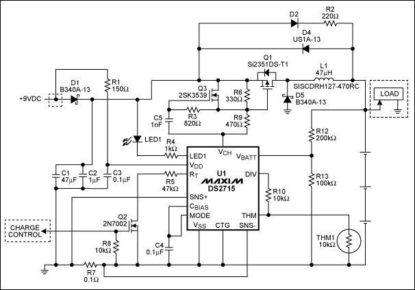
The DS2715 is a comprehensive NiMH (Nickel Metal Hydride) smart charger solution featuring load detection, making it ideal for cost-effective applications. The DS2715 smart charger integrates several key functionalities designed to enhance the charging process for NiMH batteries. It employs...
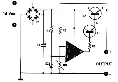
This automatic battery charger circuit is ideal for charging batteries used in alarm systems that require battery buffering. Caution must be exercised when connecting the battery to ensure correct AC polarity. It is essential to meticulously follow the schematic...
.jpg)
This is a two-phase hybrid stepping motor with a dynamic voltage range of 12 to 48V and a maximum current rating of less than 5A. The motor has an outer diameter ranging from 35 to 86 mm. The drive...
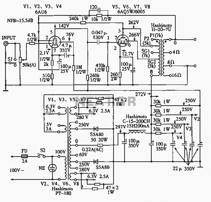
The 6AQ5W / 6005UL four-channel single-ended amplifier circuit is illustrated in the accompanying figure. Only two channels are shown, but it is part of a four-channel system that employs a power transformer for the voltage amplification section. This section...