
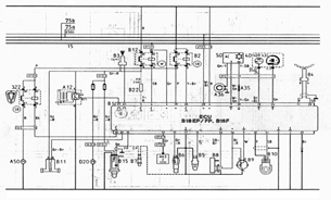
Single-ended four-channel amplifier schematic

The 6AQ5W / 6005UL four-channel single-ended amplifier circuit is designed for high-fidelity audio applications, leveraging the characteristics of the 6AQ5W and 6005UL vacuum tubes to deliver rich sound quality. The circuit employs a power transformer, specifically the Tokyo Light Sound 4CP-2508-SA type 4, which is essential for stepping up the voltage during amplification. This transformer is integrated into the voltage amplification section and is crucial for achieving the desired output levels.
The volume control is facilitated by a potentiometer that adjusts the signal level across all four channels uniformly, allowing for balanced audio output. This feature is particularly beneficial in multi-channel audio systems where consistent volume levels are required across different channels.
The output stage utilizes a UL (Ultra Linear) type configuration, which enhances the amplifier's performance by improving linearity and reducing distortion. The auditory output is further refined through a dual-path negative feedback loop. The first feedback path, which incorporates a 240kΩ resistor, connects from the cathode of the tube screen output electrode back to the primary tube. This configuration introduces a feedback amount of 6dB, which helps stabilize the amplifier's gain and improve overall sound quality.
The second feedback path is derived from the output of the transformer secondary. This path provides a higher feedback amount of 9.5dB, which further contributes to the amplifier's performance by reducing distortion and enhancing frequency response. The combination of these feedback paths allows for a well-rounded audio output, making the 6AQ5W / 6005UL amplifier suitable for various audio applications where clarity and fidelity are paramount.
Overall, this circuit design exemplifies the balance between performance and functionality, making it an excellent choice for audiophiles seeking a high-quality amplification solution.6AQ5W / 6005UL four-channel single-ended amplifier circuit shown in FIG. Shown are only - channels. 4-channel system - using a power transformer for voltage amplification section uses Tokyo light sound 4CP-2508-SA type 4 with volume potentiometer while adjusting the 4 channel volume. The output stage has a good sense of hearing UL type circuit. NFB loop two routes, all the way from the cathode tube screen output electrode via 240kQ resistance to the primary tube, the amount of feedback is 6dB, another way is taken from the output of the transformer secondary 81 "1, the amount of feedback is 9.5dB.
Related Circuits
The following document contains information related to the electrical installation schematic diagram for the Volvo 440. It includes the wiring schematic for the Volvo 440, 460, and 480 series. The Volvo 440, 460, and 480 series vehicles feature a comprehensive...
This power supply was designed for use with the Simple hybrid amplifier published elsewhere in this issue. It is suitable for various applications as well. A cascade generator is utilized for the 170 V output, a switch-mode supply provides...
18W audio amplifier constructed using transistors. The 18W audio amplifier design utilizes a transistor-based configuration to achieve efficient amplification of audio signals. The circuit typically consists of several stages, including a preamplifier stage, a driver stage, and a power output...
The input impedance can be classified into high-impedance and low-impedance inputs based on the requirements of various audio equipment and the load impedance. High-impedance input mode is typically utilized in general audio devices such as CD players, VCD players,...
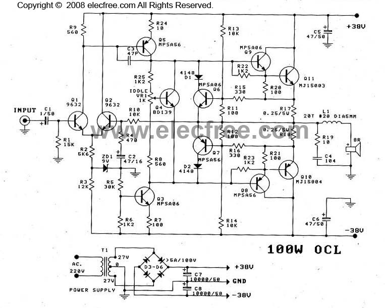
This OCL 100W power amplifier offers excellent sound quality. The circuit features direct coupling throughout to minimize low-frequency cut-off issues, enhancing super bass performance. The input signal for the tone controls enters via capacitor C1 to the base pin...
Many times we needed to use a simple circuit of preamplifier, with few components and facility of made. This circuit uses an opamp, the Motorola, TCA5550, that contains a double amplifier, as outputs for the adjust of volume, balance,...