
Single Chip Memory Call Bell

The single-chip memory call bell circuit is designed to provide a reliable notification system for visitors when the homeowner is not present. The core component of this system is the CD4011, which contains four independent 2-input NAND gates. The circuit leverages the NAND gates to create a memory function that retains the state of the doorbell even after the button is released, ensuring that the signal is captured and can trigger a notification.
When a guest presses the doorbell button, the circuit momentarily activates, sending a signal through the NAND gates. The arrangement of the gates is configured to form a flip-flop, which allows the circuit to maintain its state until it is reset. This memory function is crucial for ensuring that the signal is not lost immediately after the button is pressed.
In the schematic, the input from the doorbell button is connected to the first NAND gate. The output of this gate is fed into the second NAND gate, which is configured to create a feedback loop with the first gate. This feedback allows the circuit to maintain its output state even after the button is released. The output from the second NAND gate can be connected to an LED or a buzzer, providing a visual or audible indication of the guest's presence.
Additional components may include resistors and capacitors to stabilize the circuit and prevent false triggering. A power supply is also necessary to provide the required voltage to the NAND gates and any connected output devices.
Overall, this single-chip memory call bell circuit using the CD4011 NAND gate is an effective solution for doorbell applications, ensuring that homeowners are notified of visitors even in their absence.Single Chip Memory Call Bell using quad 2 input NAND gate CD4011 record when any guest come in absence of us.circuit diagram with description various doorbell project. 🔗 External reference
Related Circuits
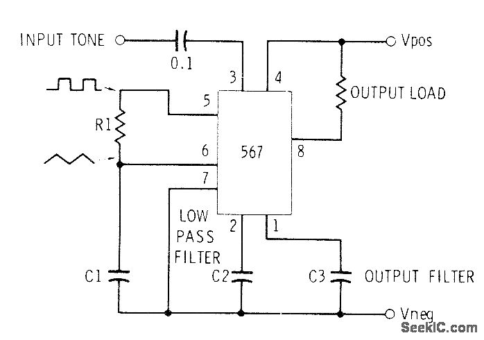
This circuit can be utilized for Touch-Tone decoding as well as for telephone line and wireless control applications using a single audio frequency. The operating center frequency is determined by components H1 and C1. The resistor R1 should be...
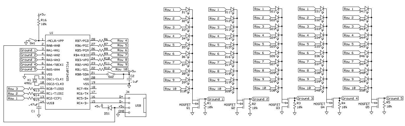
To control 40 LEDs using a single PIC 18F2455 microcontroller, the LEDs were organized into a configuration of four columns, each containing 10 rows of LEDs. Each LED in a column was connected to a separate pin on the...
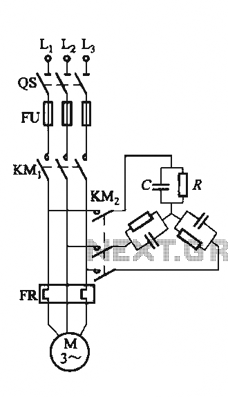
The circuit illustrated in Figure 3-151 consists of capacitor banks arranged in a specific configuration. Figure 3-151 (a) depicts capacitor banks connected in a shaped configuration, which is suitable for shaped or Y-connected motors. Figure 3-151 (b) shows Y-connected...
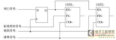
This digital frequency meter circuit is concise, with its software capabilities fully utilized. It achieves high survey accuracy in the low-frequency band while effectively preventing interference. The unique quality is demonstrated by replacing hardware components with software solutions. VHDL...
Another circuit for a balanced diet from a single voltage network. In fact, this is a uitbreding the other voltage divider circuit using a some power darling tons as buffer. This buffer can deliver a 200 to 300 mA....
This design meets the requirements through a variable gain microphone preamplifier using IC1A, a variable steep Wien-bridge pass-band filter centered around 1 kHz provided by IC1B, and an audio amplifier chip (IC2) that drives the loudspeaker. The pass-band filter...