
Single Digit E1T Clock

The control of the tube's operation involves two mechanisms. Initially, the user selects one of eight profiles during initialization, determining the hours the tube is active. For instance, a profile can be set for nighttime use only, or during specific hours such as office time. Additionally, the user can activate the tube manually by pressing a control button, extending the operation for an additional hour. Profile 1 ensures the tube remains off unless the button is engaged. Given the rarity of the E1T tube, using six of them for a single clock was not feasible. A successful one-digit NIXIE clock was previously constructed, showcasing the multiplexing of time over a single tube, which is visually engaging. The clock design requires resetting the tube for each new digit, adding an interactive element to the display.
When connecting the circuit directly to the mains, it is crucial to understand the associated dangers. Direct mains-fed circuits pose a greater risk than those using a transformer to step down voltage. In a typical scenario, a transformer reduces high voltage from the distribution grid to a usable level, such as 240V in Europe. The power is transmitted through two wires: the "live" or "phase" wire and the "neutral" or "ground" wire. Importantly, the ground wire is connected to the earth at the distribution station, providing a safety mechanism.
The E1T clock circuit design must consider these electrical safety aspects, ensuring that the connection to the mains is implemented with appropriate precautions to prevent electrical hazards. The schematic will include necessary components such as resistors, capacitors, and protective devices to ensure safe operation of the E1T tube while providing accurate timekeeping functionality.To me the E1T counting tube is unmistakably one of the most intriguing tubes ever made. It was invented and developed into a product by Philips in the period 1946-1954. On one of my other pages I have posted an in-depth study of it`s origins. It has long been my whish to build a clock with this wonderful device. One of the problems of making a clock from this tube is it`s limited lifetime. The E1T was designed for high-speed counting in measurement equipment. This was achieved by using an electron beam as opposed to a glow discharge as used in the competing decatron. This implied the use of a filament heated cathode, and unfortunately even the best filaments have a limited life expectance of ca.
10. 000 hours (1. 2 year). One of the ways to improve the life expectancy is to reduce the filament temperature. Obviously this will reduce the emission, and hence the beam current. It appears that for this application, where only low speed counting is required, a lower beam current is no problem at all. The other obvious measure to improve the life time of the tube is to simply switch it off when it is not used.
In general, the frequent on/off switching of filament heated tubes is not a good idea. A cold filament has a significantly lower resistance than a heated one. This will cause a high start-up current resulting in high mechanical stresses during the heat-up phase. This is the reason that many tubes (and light bulbs) die the moment they are switched on. In this clock the filament is not completely switched off, but kept heated at a very low level, resulting in strongly reduced thermally induced stresses.
Two mechanisms determine when the tube is actually switched on and off. In the first place the user has to select one out of eight profiles upon initialization. Each of these profiles determines during which hours of the day the tube is switched on. If e. g. the clock is situated in the bedroom, a profile can be selected so that the tube is only switched on at night. Similarly, profiles have been defined that only switch the tube on during office hours, in the evenings etc.
Additionally, it is always possible to force the tube on by pressing the control button. Each time the button is pushed the tube will stay on for an additional hour. By selecting profile 1 the clock is always off, except when the control button is pushed. The E1T tube is rather rare, and I didn`t want to use six tubes for just one clock. Recently I built a one digit NIXIE clock for my eldest son and it was a great success. The multiplexing of the time over one tube, is a bit of a puzzle and attracts a lot of attention. So obviously this was going to be a one digit clock as well. Since for every new digit the tube first has to be reset and then count to the new value, it is especially attractive because there is something to look at . In a circuit which is directly fed from the mains, the circuit is connected via a direct galvanic connection to the mains.
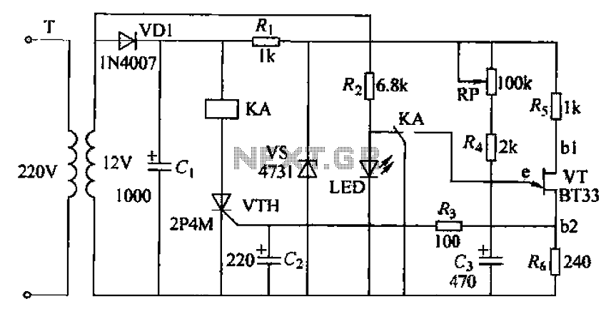
Before I start with the description of the clock circuit, I have to explain why directly mains fed circuits are so dangerous, much more dangerous than circuits that use the same high voltage but derived from a transformer. Figure 1 shows a simplified schematic drawing of the final part of the power distribution grid that delivers the power to your home, connected to an appliance that uses a transformer.
Lets for the sake of this example assume that it is a 240V to 180V transformer used to feed the NIXIE tubes. In the last distribution station the high voltage from the power grid is transformed down to e. g. 240V, the mains voltage we have in Europe. The power is delivered through two wires. One of these wires is called the "life wire" or the "phase wire". The return wire is called the "null" or "ground" wire. It is important to note that at the distribution station the ground wire is connected to ground, that is the ground that you are standi
🔗 External reference
Related Circuits
The experimenter's pot is a solid state potentiometer using Dallas semiconductor's DS1869 and National's LM78L05, two electrolytic capacitors, two small push button switches, and two optional Molex connectors. This project is very useful, especially in finding the right value...
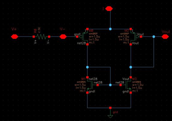
The objective of the project is to design an imager chip for laser-scanned 3-D depth/range finding. The project is divided into two modules: Pixel Array/Centroid Detection and Analog-to-Digital Conversion (ADC). The pixel array/centroid detector tracks the centroid of the...
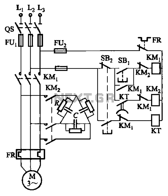
The circuit illustrated in Figure 3-151 consists of capacitor banks arranged in a specific configuration. Figure 3-151 (a) depicts capacitor banks connected in a shaped manner, which is suitable for use with shaped or Y-connected motors. Figure 3-151 (b)...
The design of the digital logic probe centers around a pair of complementary bipolar transistors, which, in this application, are used as electronic switches. The digital logic probe is a diagnostic tool utilized for testing and analyzing digital circuits. The...
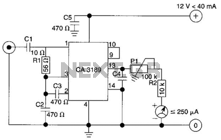
The circuit consists of a delay loop, discriminators, output circuits, power supply, and indicator lights, divided into five parts. The power regulation is achieved through a resistor (R), while the power regulator is constructed using a voltage source. In...
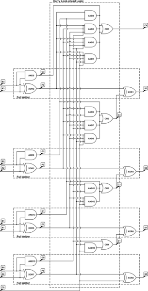
A 4-bit Carry Look Ahead Adder has 3 gate delays for all carry bits and 4 gate delays for all sum bits, whereas ripple adders have 7 and 8 gate delays, respectively. The 4-bit Carry Look Ahead Adder (CLA)...