
Single-Ic Alarm

The described auto burglar alarm circuit utilizes a single integrated circuit to streamline the design while maintaining functionality. The primary operation involves an arming mechanism activated by a switch when the user exits the vehicle, which sets the system in standby mode. The circuit employs two timers: the first timer serves as an entry delay, allowing the user a brief period to re-enter the vehicle without triggering the alarm. The second timer controls the duration of the alarm sound once the entry delay has elapsed.
The resistance value for the timing components, specifically R, is critical for ensuring that the circuit operates effectively. A resistor value of less than 1 kOhm is recommended to optimize the response time of the timers. If an incandescent lamp is incorporated in place of a resistor, the circuit gains the added benefit of providing a visual indication of an open entrance, enhancing user awareness.
To further enhance the reliability of the system, the design includes considerations for environmental factors, such as water accumulation. By selecting a low resistance value, the circuit minimizes the risk of false alarms due to moisture. Additionally, in scenarios where the door switch is wired to 12 V instead of ground, a transistor inverter is suggested to ensure proper signal processing.
The simplicity of this alarm circuit does not preclude the possibility of expanding its capabilities. Users can incorporate features such as no-entry delays for other access points, including the hood and trunk, and implement retriggering mechanisms for situations where doors are left open. This flexibility allows for customization based on user preferences and security needs, making it a versatile solution for vehicle protection. With a single IC, you can build a simple, reliable auto burglar alarm or a similar alarm. See (a) for the timing informatio n for the alarm circuit in (b). When you leave your vehicle, flip the arming switch and close the door behind you to arm the device. Subsequent opening of an entrance triggers both timers. After the expiration of the entry delay timer, the alarm sounds for a time that is determined by the second timer. The value of R should be less than 1 KOhmhm. If you use an incandescent lamp instead of a resistor, you get an extra function—an open-entrance indicator.
By keeping the resistance low, you avoid false tripping should water collect under the hood. If your door switch connects the courtesy light to 12 V rather than to ground, use a single transistor as an inverter at the input. Although this circuit"s simplicity has its drawbacks, you can add more features, such as no-entry delays for the hood and trunk, and retripping when doors remain open.
Related Circuits

If you choose to create your own moisture sensor, this foil pattern will be useful. A sensor connected to J1 activates CR1, which sounds buzzer BZ1. The sensor consists of a printed circuit board (PCB) foil pattern grid. Multiple...
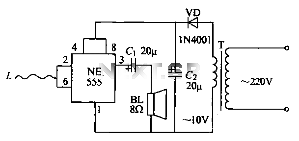
The manpower inductive alarm circuit is simple and practical. When a person's hand approaches the sensing line, the alarm emits a sound, making it suitable for male electrical burglar alarms. The induction line L is approximately 50 cm long....

When one of the switches is closed, the base of Q1 is connected to ground through D1 and R2. This activates Q1, which in turn activates Q2. Q2 connects the positive side of the relay coil to the supply...

The general-purpose circuit of the simple pressure sensor alarm is constructed using a few easily accessible and inexpensive components. The operation of this circuit is straightforward. The simple pressure sensor alarm circuit typically includes a pressure sensor, an operational amplifier...

This compact water sensor alarm circuit emits a loud warning sound when a humidity sensor detects the presence of water. The circuit utilizes the low-power comparator LM1801 from National Semiconductor. A fixed reference voltage for the integrated circuit is...

This model features a pleasant female voice activated by a button press, and includes an alarm function that can wake users up with a rooster sound at a designated time. It also announces the time every hour, which some...