
Water Sensor Alarm Circuit

The water sensor alarm circuit is designed to provide an efficient and reliable solution for water detection. The core of the circuit is the LM1801 comparator, which is configured to compare the voltage from the humidity sensor against a predetermined reference voltage set by resistor R2. This setup ensures that even minor changes in humidity levels can trigger the alarm effectively.
When the humidity sensor detects water, it generates a voltage that exceeds the reference voltage. This change is sensed by the LM1801, which then activates the piezoelectric buzzer. The buzzer is capable of producing a loud sound, ensuring that the alarm is noticeable even in noisy environments. The current requirement for the buzzer is significant, at over 24 mA, indicating that it is designed to create a strong auditory signal.
In terms of power management, the circuit is optimized for low power consumption during its idle state, drawing only 10 microamps. This characteristic is particularly beneficial for applications where long-term monitoring is required, such as in basements, near water heaters, or in outdoor settings. The use of a 9V battery allows the circuit to operate continuously for an extended period, potentially lasting up to one year before battery replacement is necessary.
Additionally, the design allows for the connection of multiple humidity sensors, enabling the monitoring of various locations with a single alarm circuit. This flexibility makes the water sensor alarm circuit suitable for a range of applications, from residential to industrial environments, enhancing its utility in water leak detection and prevention systems.This small water sensor alarm circuit makes a loud warning sound when a humidity sensor detects a quantity of water. This circuit assembly is an application of low power comparator LM1801 made by National Semiconductor.
The reference voltage for the integrated circuit is fixed with the help of R2. When pin 4 of the LM1801 voltage exceeds preset th reshold, because the moisture sensor noticed a smaller or larger chip will command the active piezoelectric buzzer with a current of over 24 mA. In the surveillance state, the water sensor alarm circuit has a current consumption of 10 microAmps so you can use a 9V battery for almost one year.
We can connect many sensors simultaneously. 🔗 External reference
Related Circuits
The problem with class-B amplifier design is that we start with an output stage in two halves, each with a non-linear response, which we then add together to try to give a linear response, i.e. so that a graph...
This circuit is designed as a warning flasher to alert road users to dangerous situations in low-light conditions. It can also function as a bicycle light, subject to applicable traffic regulations. White LEDs are recommended for use as a...
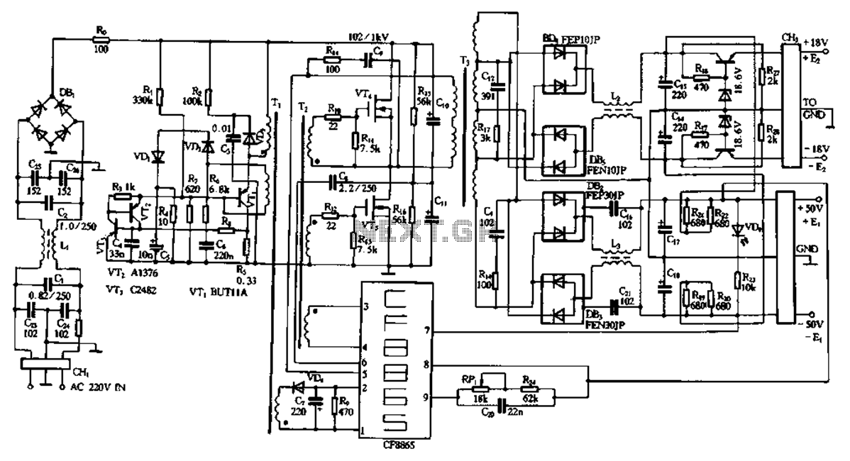
This document describes a specific module utilizing the CF8865 switching power supply circuit, which employs the integrated control module CF8865. In the figure, transistors VT4 and VTs are controlled by the excitation transformer Tz. The output is processed through...

The call is triggered by the position sensing circuit, which activates the control circuit and SOS alarm circuit. This system is designed for critically ill patients or to assist disabled individuals in the event of a fall. A position...
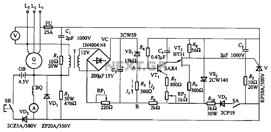
The circuit depicted in Figure 7-32 is designed for an excitation device capable of handling a terminal voltage of 400V and a capacity of less than 75kW for synchronous generator motors, enabling automatic adjustment of excitation. When the generator...
The metal detector circuit is presented here, illustrating a simple yet effective design. It utilizes a 40, 106 Hex Schmitt inverter IC, a capacitor, a search coil, and batteries. An advantage of connecting IC1b Pin 4 to a medium-wave...