
Single-junction transistor sine wave oscillator circuit

The single-junction transistor serves as a fundamental building block in various oscillator circuits due to its simplicity and efficiency. In the context of a sawtooth generator, the transistor can switch rapidly, creating sharp transitions that are ideal for generating sawtooth waveforms. The addition of an LC tuned circuit enhances the functionality of the oscillator by allowing it to produce sine wave oscillations.
In this configuration, the LC circuit, which consists of an inductor (L) and a capacitor (C), is tuned to resonate at a specific frequency determined by the values of L and C. When the single-junction transistor is excited by a current pulse, it drives the LC circuit into oscillation. The resonant frequency of the LC circuit can be calculated using the formula:
\[ f = \frac{1}{2\pi\sqrt{LC}} \]
where \( f \) is the frequency in hertz, \( L \) is the inductance in henries, and \( C \) is the capacitance in farads.
The tuned resistor R1 plays a critical role in controlling the amplitude of the oscillations. By adjusting the resistance value, the current flowing through the circuit can be modified, which in turn affects the output sine wave's amplitude at point B2. This feature allows for fine-tuning of the oscillator's output, making it versatile for various applications in signal processing and waveform generation.
Overall, the design's minimal component count combined with the effectiveness of the single-junction transistor and LC tuned circuit makes it a valuable solution for generating precise waveforms in electronic applications.The single-junction transistor is always used in the sawtooth generator and pulse generator, and it also can form the simple sine wave generation circuit. As an oscillator circuit of the discrete component, it uses fewest components. As the figure shown, compared with the simple single-junction tube remittent oscillator circuit, this circuit adds
a LC tuned circuit at the second base. By the excitation of the single-junction tube current pulse, the tuned circuit generates sine wave oscillation. Tuned resistor R1 can control the size of current pulse and have the sine wave at B2. 🔗 External reference
Related Circuits
This circuit allows for the control of any line-powered electrical device, such as a lamp, television, or fan, using any infrared remote control. Many individuals possess a collection of old IR remotes from appliances that are no longer in...
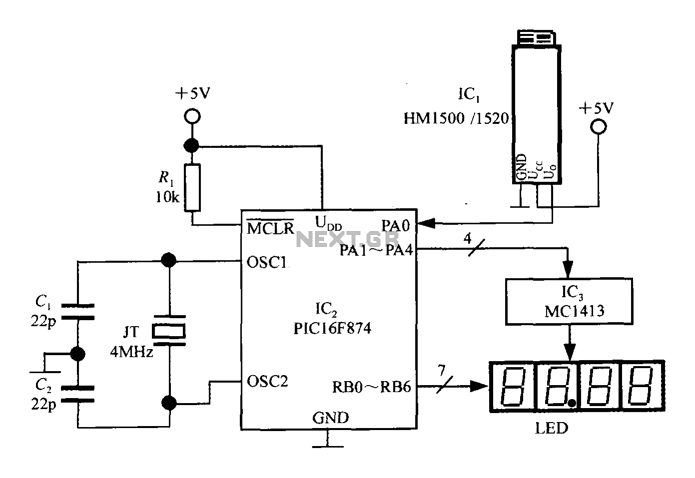
An intelligent humidity meter circuit utilizing the HM1500/1520 humidity sensor and a microcontroller configuration. The circuit operates on a +5V power supply and incorporates four common cathode LED digital displays. It employs three integrated circuits: IC1 is the HM1500/1520...
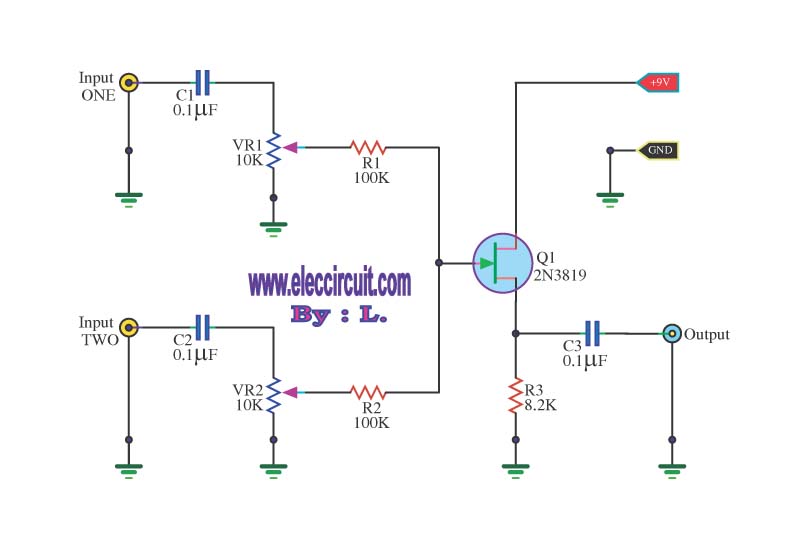
This circuit is a simple mixer circuit that can mix two signal channels into one output channel. It utilizes a codec circuit to convert stereo audio to mono audio. The main component in this circuit is a FET, specifically...
An average ability amplifier characterized by acceptable overall quality, while being simple in construction. It is frequently used in live loudspeakers. The design incorporates high-quality FET transistors, specifically HEXFET technology, which are voltage-controlled rather than conventional bipolar transistors. The...

The circuit primarily comprises a 60-Hz sine-wave oscillator featuring a 10K frequency-control potentiometer, two buffering stages, and a push-pull power amplifier. This design effectively addresses the noise issues associated with square-wave inverters, particularly when powering a 115-V radio receiver...
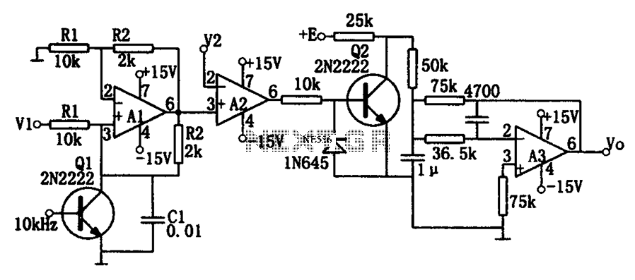
As illustrated in the dividing circuit diagram, A1 consists of a voltage-controlled current source, A2 functions as a voltage comparator, and A3 is configured as an active low-pass filter. When the time constant R1C1 is equal to the clock...