
Single Meter Clocks

The circuit employs a combination of digital logic components and analog signal processing to achieve a functional and visually informative display for timekeeping. The use of a quad 2-input AND gate (4081) allows for efficient signal conditioning and reset functionality, while the homebrew DAC facilitates the conversion of digital outputs from the counters into usable analog signals for the meter display. The resistor ladder, formed from carefully recorded resistance values, ensures precise analog representation of the digital time values. The integration of the 74HC4851 analog switch enables seamless selection between multiple analog signals, enhancing the versatility of the display system. The adjustable frequency of the 555 oscillator allows for user control over the display refresh rate, providing a tailored user experience. The elimination of traditional switches for time setting in favor of pushbuttons simplifies user interaction, while the overall design prioritizes safety and reliability through the careful selection of power supply components. This innovative approach not only enhances the aesthetic and functional qualities of the nixie clock but also demonstrates an effective use of electronic components to create a cohesive and efficient timekeeping solution.An alternating display for my version 1 nixie clock led me to think of new logic designs for switching signals to the display. I took the design of my version 1 nixie clock, tossed out the 4013 flip flop and two 4017 counters, and redesigned the hours section and the reset circuits.
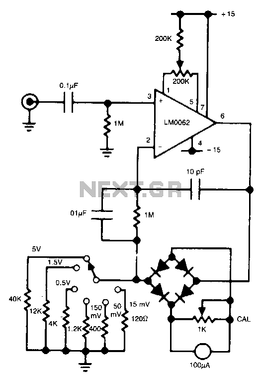
A 4081 (quad 2-input AND gate) was used instead; a single gate serves as a Set/Reset bistable, another gate basically takes in the signal when the hours reach 13 and goes HIGH to reset the hours, and the last two gates serve as buffers (one for the 60Hz line). There were several modifications mainly to drive a single meter (the meter used is a Heathkit "Antenna Impediance Meter" or a 0-100uA meter).
The outputs of the 4017s were converted to analog signals using a homebrew DAC with a chain of transitors and resistors. First, a 500K pot was used and wired with one transistor in series. Tune the pot to one digit on the meter, record the resistance of the pot, retune the pot to the next digit, record the resistance, and so on.
A resistor ladder was created from the recorded resistances to convert the digital signals to analog signals. For the meter to display 0, the resistance is open and the meter outputs nothing. For the meter to display 1, the signal has to go through the entire resistor ladder (total of about 520K), for 2, it goes through less resistance, and so on until the least resistance causes the meter to display 9 (maximum).
The clock circuits are always on so there are always four analog signals being produced. A 74HC4851, a cool 8-channel analog switch mainly for audio, is used to switch one of the four analog signals to the meter. A separate 4017 and a free running 555 oscillator set to be variable from around 1/4Hz to 1Hz is used to switch the channel inputs on the 74HC4851 to allow the display speed to be adjustable.
Another modification I made to the circuit was to eliminate the FAST and SLOW set switches. Of course, this method would be terribly difficult to set the time while only being able to view one digit at a time. Instead, a pushbutton is used to set the hour and another pushbutton to set the minutes. The power supply is relatively safe consisting of only a 25VCT transformer that was found in my junk pile and produces about 13VDC after rectification.
The 13V is then reduced and regulated to 5V with the 7805. The 60Hz signal is obtained from one side of the transformer before the rectifiers. Four LED displays were wired off the 4017 chip that switches the channel inputs on the 74HC4851 to light in sequence. Notice that channel 1 (Y0) on the 74HC4851 and output 1 (Q0) on the 4017 are left disconnected. This is so on the first output of the 4017, no signal is passed into the channel selector inputs, so they are pulled down to LOW via the 6K resistors and the 74HC4851 is automatically on channel 1 (Y0).
As a result, the meter and the LED indicators are off. I call this the blank state so the viewer would know that the meter is just about to start displaying the time. Finally, when output 1 of the 4017 goes HIGH, the channel increments to the second channel (Y1) so the meter displays the 10 hour (either 0 or 1), and the first LED is lit.
The next output of the 4017 selects channel 3 (Y2), meter displays the 1 hour (0-9), and the second LED lights. The fourth 4017 output selects channel 5 (Y4) because the binary input is 100 (4) and the meter displays the minutes.
Finally, the fifth output of the 4017 will activate both input B and C for a binary value of 110 (6) to select channel 7 (Y6) to display the minutes. This is an easy way to avoid using unnecessary logic gates to decode decimal into pure binary or vice versa.
The display cycle starts all over again when the 4017 goes to the 6th output (Q5) and resets itself to bring the meter back into the "blank state. " The second single meter clock design is much simpler and runs off a PIC 16F84A micr 🔗 External reference
Related Circuits

A device designed for measuring time and temperature used in chemistry laboratory. The circuit employs a 89C4051, 20-pin CMOS Microcontroller with built-in 4kB code memory. Temperature was measured by LM35D, National Semiconductor Temperature sensor producing 10mV/°C. The CA3162, 3-digit...
In this circuit, a diode bridge is utilized as a meter rectifier. The offset voltage is compensated for by the operational amplifier, as the bridge is part of the feedback network. The circuit employs a diode bridge rectifier, which consists...
As an essential component of an advanced computer science course focused on microcomputer systems, it was determined that students would benefit from the design of a single-board computer system utilizing a widely available microprocessor. This decision led to the...
This simple circuit makes it possible to monitor the charging process to a higher level. If you need more information then check out the LM3914 Datasheet. Final adjustments are simple and the only thing needed is a digital voltmeter...
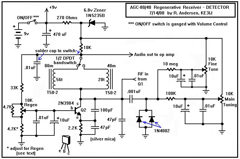
Here is a dual-band regenerative receiver that originated from encouraging communications with Jerry (K9UT) and another individual named Harvey, who constructed the original AGC-80 and its experimental successor, the AGC-80/30. Jerry has expressed his satisfaction with both receivers, noting...
The 1N4001 is a 1 Amp silicon rectifier with a voltage range of 50 to 1000 volts. It features guaranteed high-temperature soldering, high current capability, a diffused junction, low reverse leakage, and utilizes a void-free molded plastic technique for...