
Build a Crystal Shortwave Radio
The EconOceanic Crystal Shortwave Receiver project exemplifies the blend of historical radio technology with modern construction techniques. The design emphasizes simplicity and accessibility, allowing enthusiasts to engage with radio frequencies without the need for complex electronic components. The crystal receiver operates on the principle of harnessing ambient radio waves, making it an excellent project for those interested in the fundamentals of radio communication. The tuning range encompasses both the AM broadcast band and a significant portion of the shortwave spectrum, providing a rich listening experience that includes international broadcasts, amateur radio transmissions, and precise time signals.
The assembly process is structured to facilitate ease of construction while ensuring that the finished product is user-friendly and aesthetically pleasing. The use of readily available components and the emphasis on DIY construction make the EconOceanic a practical project for hobbyists and educational purposes. The detailed instructions for winding coils, drilling holes, and assembling components ensure that builders can achieve a high level of functionality and performance in their finished radio.
In summary, the EconOceanic project stands as an engaging opportunity for individuals to explore the world of radio technology while appreciating the historical significance of crystal radios and shortwave listening. The combination of user-friendly design, accessible components, and the rewarding experience of building a functional radio receiver makes this project a noteworthy endeavor for electronics enthusiasts.This project combines two popular themes from radio history ”crystal radios and shortwave (SW) listening. It`s designed from scratch by our non-resident engineer Walter Heskes. Despite all of the advances in modern electronics, there are thousands of crystal sets in daily use throughout the world.
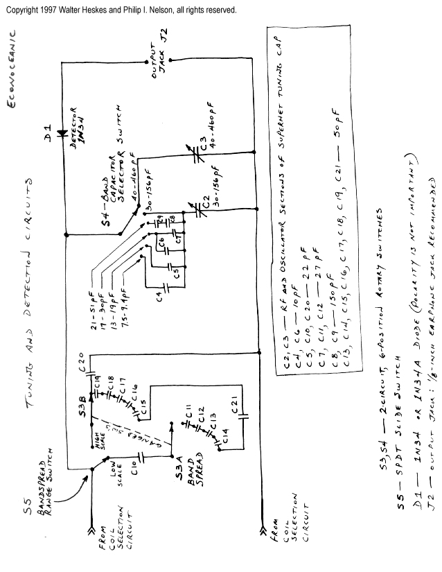
The fidelity of tone and clarity of crystal rect ification are hard to beat. What`s more, crystal sets are absolutely free! A crystal receiver is powered solely by the radio waves that it pulls from the air. We dubbed this inexpensive radio the "EconOceanic" in honor of the legendary Zenith TransOceanic family of shortwave radios. It tunes the AM broadcast band, from. 5 MHz to 1. 6 MHz, and most of the shortwave band, from 1. 7 MHz up to about 17 MHz. There`s plenty of SW activity in these bands, so you`ll hear lots of different voices, a mix of languages, and even music.
In addition to powerhouse stations such as the BBC, you`ll also hear non-commercial amateurs, some of whom broadcast using the dits and dahs of International Morse Code. And don`t forget to set your wristwatch by the precise WWV time signals. They appear at exact multiples of 5. 0 MHz across the SW bands. Listen for the calibration beeps and periodic time announcements. We hope you enjoy this project. If you build an EconOceanic, send some email to let us know how it worked out. Walter can be reached at walterh@interworld. com. The large diagrams are designed to print on a standard 8. 5 x 11-inch sheet of paper. Most of them are oriented horizontally for easier reading online. Choose your printer`s "landscape" mode for the horizontal diagrams, to make sure they`ll print on one sheet.
Be sure that your printer is set to print at a 1-to-1 ratio, so that the cabinet decal and layout diagram are the correct size. We recommend getting all of the parts you need before you start assembly. Nothing is more frustrating than getting halfway through a project, then having to wait several days for some missing part to arrive in the mail.
Most of the parts you need to build the EconOceanic Crystal Shortwave Receiver are available through Radio Shack. Two exceptions are the big tuning capacitor and the little trimmer capacitor. The big tuning capacitor can be obtained from Antique Electronic Supply. Or, you may be lucky enough to have a spare tuning capacitor in your junkbox. The small trimmer capacitor is available from All Electronics, allcorp@allcorp. com, 1-800-826-5432. Some notes on specific parts appear after this list. 2 A variable air capacitor can be scrounged from any old AC/DC superheterodyne AM radio. Use the RF section for the wide range (40-460 pF) and the oscillator section for the narrow range (30-156 pF) 3 Bags of ceramic capacitors are available in large quantities from Antique Electronic Supply and Radio Shack.
These capacitors will work fine, but if you buy them in bulk, you may need to identify them using their markings or by reading them with a capacitor meter. 5 Enamel-coated wire is available from Radio Shack and other suppliers. Radio Shack part no. 278-1345 is a package of three spools of enameled wire in the following sizes: #22 (gold enamel), #26 (green enamel), and #30 (red enamel), all for $3.
99. If you don`t see it on display, find it in the catalog and point it out to the clerks so they will order it for you. 6 It`s not critical which type of glue you use to fasten the metal frame of the tuning capacitor to the plastic surface of the instrument panel.
Epoxy glue (JB weld or similar) will work, and so will silicon-based glues and perhaps others. 9 If you choose to use an amplified speaker (highly recommended), use a short coaxial cable terminated with 1/8" plugs on both ends to connect the EconOceanic output to the speaker. 10 One of the fuse holder clips is modified to form a swiveling support for the antenna mast, as explained in the building instructions.
To fasten the antenna mast assembly to the cabinet, you`ll also need a small screw, rubber washer, metal washer, lockwasher, and nut. If you don`t have those items lying around somewhere, your house is cleaner than ours! Let`s go! The first major step is to drill mounting holes for the controls in the plastic cabinet. The entire radio is mounted to the front panel, making it easy to remove for modifications or simply for showing a friend your handiwork.
The Component Layout Diagram and Cabinet Decal show you where to drill holes in the cabinet front panel for the components. Carefully trim the decal to fit the cabinet, then punch or cut holes in the decal where indicated. Glue on the decal. Don`t put any glue under the places where you`ll be drilling holes. Using a scribe or sharp knife, and guided by the scribe marks on the decal, make a little guide hole in the exact center of each place to drill.
Using a sharp knife, carefully trim away the paper from each hole, so the drill won`t tear the paper. Regarding the decal, not all printers are created equal, so make sure it`s printed at the right size before gluing it on.
At the correct size, the decal measures 7. 5 inches wide (horizontally) at the trim lines. If you can`t get it to print correctly, you can try loading the image into a graphics program such as Photoshop or Paintshop Pro and resizing it for a new printout. The component layout diagram gives exact measurements for the holes, in any case. Before you drill any holes, check clearances by placing the actual knobs in place atop the diagram. Now drill the holes. Drilling plastic is fast and easy. Wear protective eyegear to guard against flying fragments of plastic. If you`d like to protect the paper decal against dirt and wear, spray on a thin coat of clear lacquer or poly finish, then set it aside to dry.
A more permanent solution would be to have it laminated beforehand at a local copy shop. Finally, mount the components in the positions shown in the component layout diagram. Pop the front panel into the case and admire your work. From the outside, this project looks almost finished ”all that`s left is to build the radio that goes inside! Switchable coils are a unique feature of the EconOceanic. With many old shortwave radios, changing bands required you to unplug one coil and plug in another. With the EconOceanic, you simply turn switches to change coils in or out. That`s more convenient, and it reduces wear and tear on the coils. In the EconOceanic, all of the BC and SW coils will be wound on a single core. The first step is to get something to wind your coils on. A standard roll of paper towels comes on a 1 5/8-inch diameter cardboard tube, which is just right. Although you can wind the coils on a single tube, it`s a good idea to reinforce the tube with a second stiffening layer, to help resist the tension of the wire as you wind the coils.
To create the reinforcement, get an extra cardboard tube, slice it down its length, and remove a 3/8-inch wide strip along the cut, thus reducing its diameter. (Remember that this inner tube has to fit inside another tube of the same original diameter. ) Apply a thin layer of Elmer`s Glueall to the entire outer surface of the inner tube and insert it through the outer tube.
Let it expand and gently press the tubes together to spread the glue. Hold them together for a couple of minutes, then set them aside for the glue to dry. Now you have a single, thick core. This design requires precise winding, which will be easier if you take a moment to mark your core with lines along its length to indicate its halves, quadrants, and eighth-sections. (In other words, draw eight equally-spaced straight lines, each one going the entire length of the tube.
) When you need to wind a coil of 22 3/4 turns, you`ll know exactly where to stop during the 23rd turn. The more accurate your coils, the better they`ll work. A coil with the wrong number of turns provides the wrong inductance and will not tune the desired range of frequencies.
It`s time to start winding, a task that requires care. Here`s a little trick that simplifies the process. As you wind each coil, it helps to apply a thin layer of Elmer`s Glueall to hold the most recently wound section together. Otherwise, the wires tend to spring apart (if that happens, you have to rewind the coil from scratch.
) Wind about 10 turns, hold them tightly in place with your thumb, apply a pea-sized glob of glue to the wound section, and spread it with the middle finger of your other hand. Work the glue between the coils to encapsulate them. The thin layer dries in a few seconds and you can quickly continue winding. It`s a technique you can develop pretty quickly. By the time you`ve wound all 101. 5 turns of the big broadcast (BC) band coil, you`ll feel like an expert! Wind one coil at a time, following the Coil Winding Diagram. Use a full spool of wire when you start winding the big BC coil. It can be heartbreaking to run out of wire just before you reach the end. Leave 10 inches of extra wire at each end of each coil. It is better to have extra length now which can be trimmed away later. These ends are the leads that you`ll connect to the other components. Mark each lead wires using a little flag of masking tape (for instance, "250 uH Antenna" and "250 uH Ground").
The markers will simplify hookup later on. The chart below lists the number of turns and size of wire to use for each coil. This radio tunes five bands. Each band requires a pair of windings: a small primary and a larger secondary. 🔗 External reference
Related Circuits
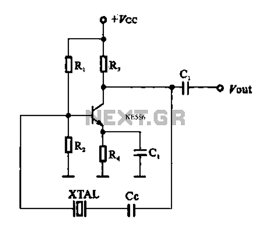
A series resonant circuit utilizing a crystal oscillator is illustrated. The crystal impedance reaches a minimum value at the series resonance frequency, resulting in a significant feedback amount. The crystal tuning capacitor (Cc) can slightly adjust the resonance frequency...
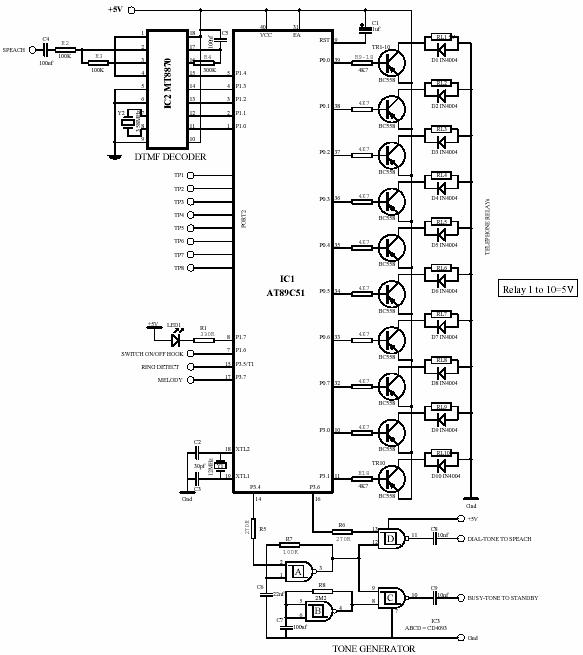
The main power source is 220V AC, which is stepped down to 24V and 72V. The 18V DC is used for the telephone system, while the 72V AC supply is used for ringing telephone bells, which is controlled by...
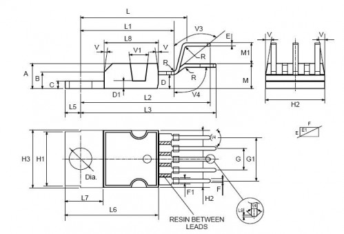
This circuit illustrates a Car Radio Audio Amplifier using the TDA2003 integrated circuit. The datasheet for the TDA2003 includes electrical characteristics and schematic wiring details. The TDA2003 is a high-performance audio amplifier designed for automotive applications. It is capable of...
This is a simple hardware computer interface and Linux program that can be used to control the most commonly used buttons on any consumer Family Radio Service (FRS) or General Mobile Radio Service (GMRS) radio. There are 22 available...

The radio is a single-tuned set featuring dual 365 capacitors for tuning on both the antenna and detector sides of a single coil. The coil is designed with multiple taps, a concept that was initially unfamiliar but intriguing. The...
Here is something that may interest crystal radio builders: a one-transistor (silicon) AM broadcast receiver that derives its power from ambient AC hum and static. The schematic is adapted from Darryl Boyd's "Stay Tuned" website, which features over 170...