
Single-phase motor stepless thyristor circuit 2

The circuit utilizes a unidirectional thyristor, also known as a silicon-controlled rectifier (SCR), which allows current to flow in one direction only. This characteristic is fundamental in controlling the power delivered to the motor. The thyristor is triggered into conduction by a gate signal, which can be controlled by the adjustment of the potentiometer RP.
The potentiometer RP is connected in such a way that its resistance can be varied, thereby altering the voltage applied to the gate of the thyristor. By adjusting RP, the phase angle at which the thyristor is triggered can be modified, leading to changes in the average voltage supplied to the motor. This results in a corresponding change in the motor's speed.
The circuit may also include additional components such as diodes for protection against reverse voltage, capacitors for filtering, and resistors to limit current. The configuration of these components is essential for ensuring stable operation and preventing damage to the thyristor and motor.
In practical applications, this type of circuit is often used in variable speed drives for DC motors, where precise control over speed is necessary for various industrial and automation tasks. The simplicity of the design combined with the effectiveness of the thyristor control makes it a popular choice in many electronic speed control applications. Circuit shown in Figure 3-11. It uses a one-way thyristor control. Adjustment potentiometer RP, continuously changing the motor speed.
Related Circuits
The metal detector circuit is shown here that the limits represent the sake of simplicity for a metal detector, but the design works remarkably well. It only uses 40,106 Hex Schmitt inverter IC, a capacitor and a search coil...
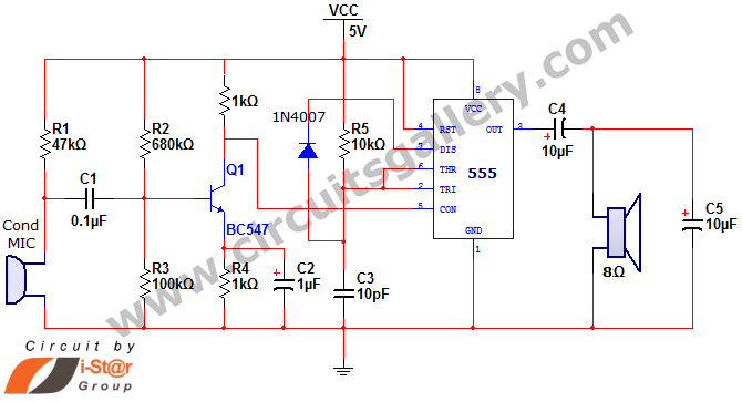
This document discusses a simple project utilizing the 555 timer IC. The 555 timer IC can be configured as an audio amplifier using an astable multivibrator configuration. It performs pulse width modulation (PWM) on an audio signal. The current...
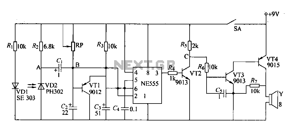
The circuit is designed to detect clogging in a wheat planter by utilizing light-emitting diodes (LEDs) and photodiodes. When the light path is obstructed by particles, the photodiode receives less light, causing the resistance of VD2 to increase. This...
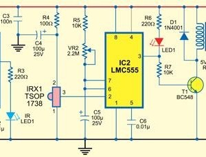
This type of infrared proximity circuit is commonly utilized as an electric switch where physical contact is undesirable for hygiene reasons. For instance, infrared proximity sensors are frequently found in public drinking fountains and washrooms. The straightforward circuit described...
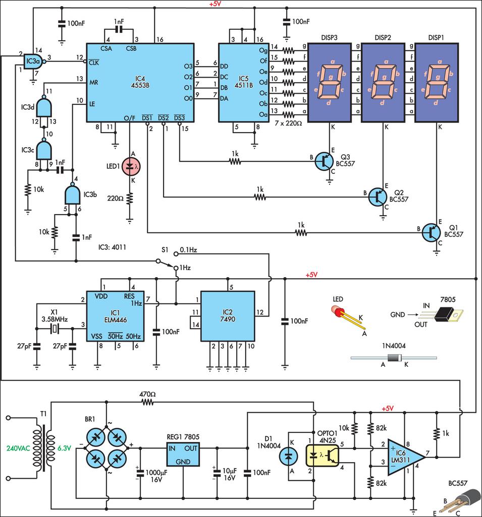
This is a simple frequency counter designed to monitor the 240VAC mains supply. It has a frequency range of 0-999Hz, making it suitable for use with 400Hz equipment as well. Standard TTL/CMOS logic is utilized for the counters and...

This circuit is a Phase-Locked Loop (PLL) system designed for use as an FM demodulator. The output of the Voltage-Controlled Oscillator (VCO) follows the FM signal, with the input voltage to the VCO being proportional to its output frequency....