
Electronic dog repellent project

The electronic dog repellent circuit utilizes an ultrasonic transmitter to emit sound waves at frequencies above the audible range for humans, typically around 20 kHz to 40 kHz. This frequency is unpleasant for dogs and cats, effectively deterring them from approaching the area where the device is deployed.
The circuit generally consists of several key components: a power supply, an oscillator circuit, a modulator, and a piezoelectric ultrasonic transducer. The power supply can be a battery or a wall adapter, providing the necessary voltage and current for the circuit operation.
The oscillator circuit generates a high-frequency signal, which is then modulated to create varying sound patterns that enhance the repelling effect. This modulation can be achieved using a simple transistor-based oscillator or a more complex microcontroller setup that allows for programmable frequency variations.
The piezoelectric ultrasonic transducer converts the electrical signals from the oscillator into ultrasonic sound waves. The design of the transducer is crucial, as it determines the efficiency and range of the emitted sound.
For optimal performance, the circuit may include additional features such as a motion sensor to activate the ultrasonic transmitter only when animals are detected, thereby conserving power and extending the device's operational life.
In summary, this electronic dog repellent circuit is an effective solution for deterring unwanted animals using high-frequency sound waves, leveraging key electronic components to achieve its purpose.The electronic dog repellent circuit diagram below is a high output ultrasonic transmitter which is primarily intended to act as a dog and cat repeller, wh. 🔗 External reference
Related Circuits
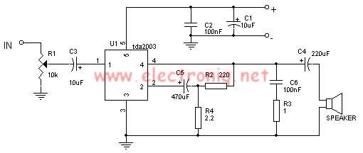
The TDA2003 audio amplifier integrated circuit can be used to design a straightforward 10-watt power audio amplifier for a 2-ohm load or 4 watts for a 4-ohm load. The TDA2003 offers high output current capacity (up to 3.5A) and...

The term "pentester" refers to a penetration tester, individuals who assess security vulnerabilities. Many high-end hotels globally depend on keycard locks for securing hotel rooms. However, recent incidents of theft have shown that these locks may not be as...
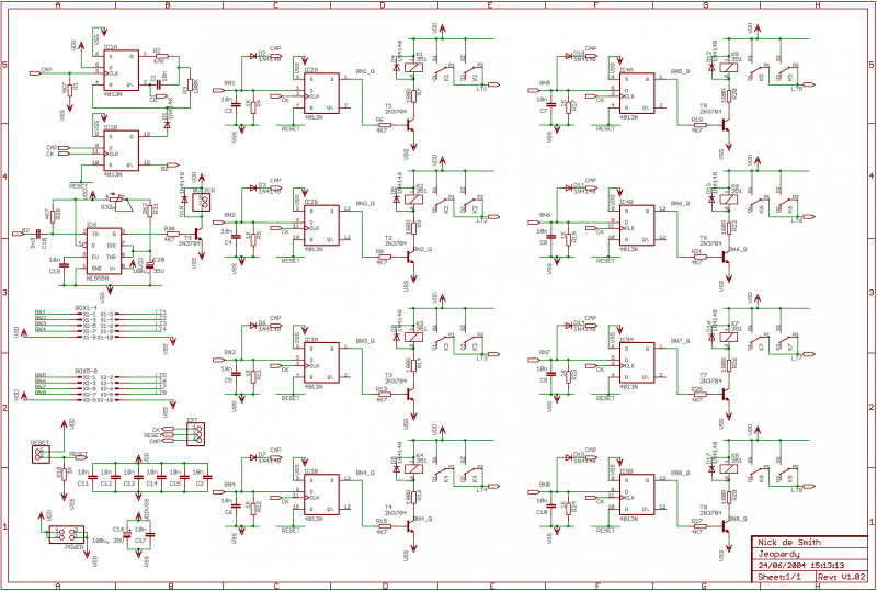
If 12V relays are used, you can replace the 180R resistors R7, R9, R14, R16, R20, R22, R26, and R28 with a wire link (the resistors are only there to limit current if you use 5V relays, of which...
Power-saving electronic mousetrap. This example describes the minimal power consumption, which only occurs when a mouse enters the control zone during foraging activities. After a 30-second delay, the system enters a wait state, making it suitable for outdoor use....
The conversion of a circuit from NPN to PNP configuration is in progress, along with a switch in polarity. Parts are being ordered for this modification. The conversion from an NPN to a PNP transistor involves several key changes in...
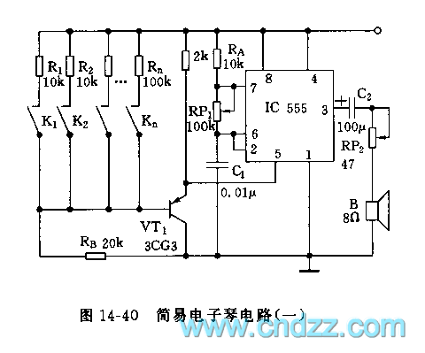
The controllable multivibrator, as illustrated in figure 14-40, consists of a 555 timer along with resistors RA, RP1, and capacitor C1. The oscillation frequency is influenced by the control voltage applied to pin 5. This control voltage is determined...