
Small High Quality Audio Power Amplifier

This audio power amplifier circuit is designed to enhance audio signals for portable devices and headphones, providing improved sound quality and volume. The simplicity of the circuit allows for easy integration into various applications, making it an ideal choice for both hobbyists and professionals.
The amplifier typically consists of a few key components: a power supply, an operational amplifier (op-amp), resistors, and capacitors. The power supply provides the necessary voltage and current for the amplifier to function effectively. The op-amp acts as the core amplification element, receiving the input audio signal and increasing its amplitude.
Resistors are used to set the gain of the amplifier and to stabilize the circuit, while capacitors may be employed for filtering purposes, ensuring that only the desired frequency range is amplified. The design may also include a feedback loop to improve linearity and reduce distortion, which is crucial for maintaining audio fidelity.
For portable applications, the circuit can be powered by batteries, and considerations for power efficiency are important to prolong battery life. Additionally, the layout of the circuit board should minimize noise and interference, which can degrade audio quality.
Overall, this audio power amplifier circuit represents a versatile solution for enhancing audio output in a compact and efficient manner.This audio power amplifier is very good for your portable devices, or for your headphones amplifier. The circuit of this audio power amplifier is very simple,.. 🔗 External reference
Related Circuits
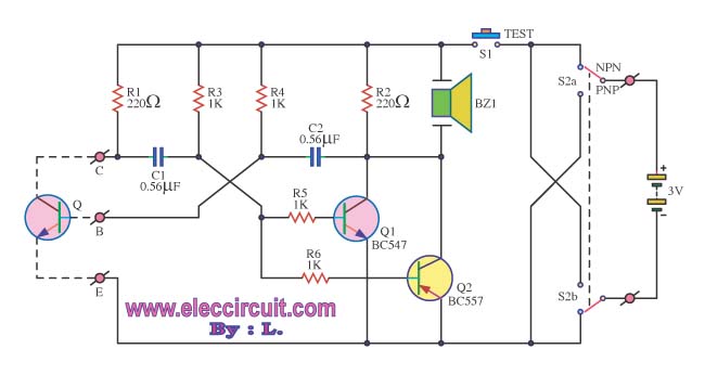
The transistor was checked by measuring the resistance between its various pins. Occasionally, issues arise when measuring the resistance between them. The process of measuring resistance in a transistor is an essential diagnostic technique used to evaluate its functionality. A...
The 15V zener is fed via the 4.7k resistor from the input. With 0.6V across the base-emitter of the PNP transistor, this establishes a voltage of 14.4V across the 3.3k resistor, so there must be a current of nearly...
This sound effects circuit is designed to function as a signal distorter. When utilized with an electric guitar, it enables the creation of unique sound effects. The sound effects circuit operates by manipulating the input audio signal from the electric...
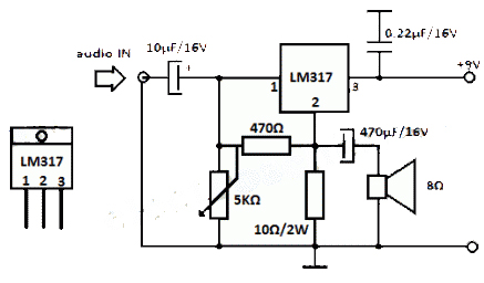
The LM317 integrated circuit (IC) is commonly recognized as a voltage regulator; however, it can also function as an audio amplifier. This low-power amplifier circuit designed with the LM317 provides a maximum output of approximately 1 watt. The LM317...
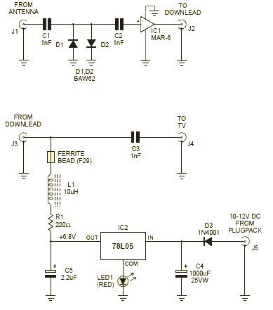
This wideband amplifier circuit is designed using the MAR-6 IC manufactured by Mini Circuits. The MAR-6 VHF-UHF wideband amplifier circuit provides a stable gain of at least 9 dB up to 2 GHz. Since the MAR-6 is designed to...
The preamp featured has optional tone and balance controls which may be omitted if desired. The input switching may be extended if needed to accommodate more signal sources. In this version, no RIAA (phono) input is provided. See the...