
Transistor quality checker with buzzer

The process of measuring resistance in a transistor is an essential diagnostic technique used to evaluate its functionality. A transistor typically has three terminals: the collector (C), the base (B), and the emitter (E). The resistance measurements between these terminals can provide insights into the operational status of the device.
When conducting resistance measurements, a digital multimeter (DMM) is commonly utilized. The multimeter is set to the resistance (ohm) mode, and the probes are placed on the respective terminals. For example, measuring the resistance between the base and emitter terminals (R_BE) should yield a low resistance value in the forward-biased condition and a high resistance in the reverse-biased condition. Similarly, measuring the collector-emitter resistance (R_CE) can indicate whether the transistor is functioning correctly; a low resistance suggests that the transistor is in saturation, while a high resistance indicates it is in cutoff.
Common issues that may arise during these measurements include open circuits, short circuits, or unexpected resistance values, which could indicate a faulty transistor. If the resistance readings are inconsistent or outside the expected range, further testing or replacement of the transistor may be necessary. It is also important to ensure that the transistor is not connected to any circuit during resistance measurements to prevent erroneous readings.
In summary, measuring the resistance between the pins of a transistor is a critical step in troubleshooting and ensuring the reliability of electronic circuits. Understanding the expected resistance values and conditions can aid in identifying potential problems and maintaining circuit integrity.You checked the transistor by measuring the resistance between the different pins. Sometimes it has problems, such as when measuring the resistance between the. 🔗 External reference
Related Circuits
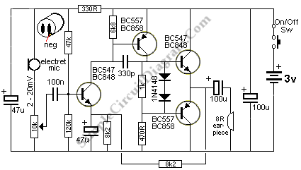
The output of this circuit is push-pull and consumes less than 3 mA (with no signal) but drives the earpiece to a very loud level when audio is detected. This circuit operates in a push-pull configuration, which allows it to...
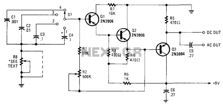
Seven narrow pulses ranging from 2 Hz to 50 kHz are generated by this circuit. Capacitors C1 through C4 provide frequency ranges in decode steps. Resistors R1 and R2 regulate the charging time of capacitors C1 through C4. R2...
Rsense will cause Q2 to conduct when a threshold of approximately 0.65V is reached. Rbias will determine the extent of this limitation, although this aspect remains unclear. Particularly, if Rsense is positioned on the high side, simply activating Q2...
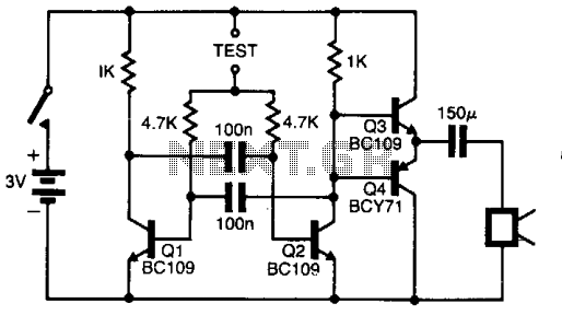
The pitch of the tone is dependent upon the resistance under test. The tester will respond to resistance of hundreds of kilohms, yet it is possible to distinguish differences of just a few tens of ohms in low-resistance circuits....
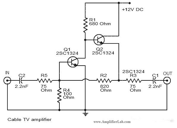
The circuit diagram of a cable TV amplifier has been provided. This cable TV amplifier circuit includes two transistors, Q1 and Q2. The cable TV amplifier circuit is designed to enhance the signal strength of cable television signals, improving the...
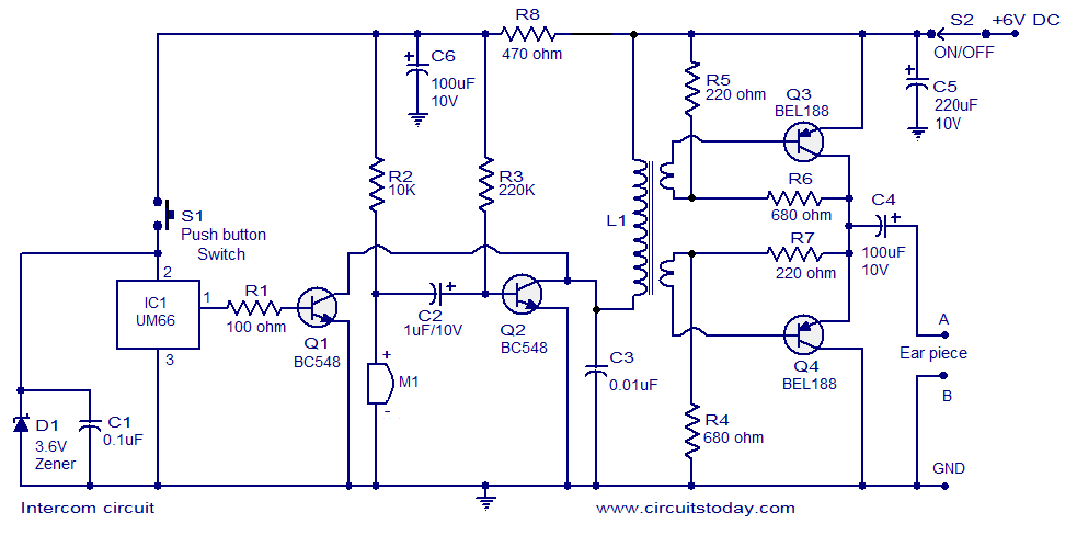
A straightforward intercom circuit designed using transistors. It does not require a changeover switch and can be used similarly to a telephone. This intercom circuit utilizes transistors to facilitate communication between two or more stations without the need for complex...