
Motion Detector Alarm Circuit

The motion detector alarm system operates on the principle of infrared (IR) detection, leveraging the HOA1405 module which consists of an IR LED (transmitter) and a phototransistor (receiver). When a person moves within the detection range of 1 meter, the IR light emitted by the LED is interrupted, causing a change in the light received by the phototransistor. This interruption is processed by the alarm circuitry, which triggers an alert signal.
The circuit typically includes a power supply, often a battery or DC power source, to provide the necessary voltage for the IR module. The output from the phototransistor can be connected to a microcontroller or a simple comparator circuit that amplifies the signal and activates an alarm system, such as a buzzer or LED indicator, when motion is detected.
For optimal performance, the IR module should be positioned at an angle that maximizes the coverage area, ensuring that the detection zone is effectively monitored. Additional components may include resistors to limit current through the IR LED, capacitors for noise filtering, and a relay or transistor switch to control higher power devices for the alarm output.
Overall, this motion detector alarm is a compact and efficient solution for security applications, providing reliable detection capabilities in a straightforward design.This motion detector alarm can detect a moving person from a distance of 1 meter. It uses a dual IR Transmitter-Receiver module HOA1405. When the sensor de.. 🔗 External reference
Related Circuits
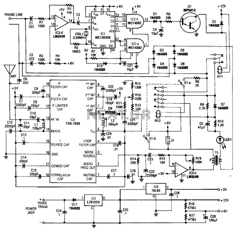
When the asterisk (*) is pressed on the touch-tone phone, a DTMF decoder, referred to as TCI, manages the on-hold logic. Audio from the FM receiver IC4 is transmitted over the telephone line when a hold condition is active....
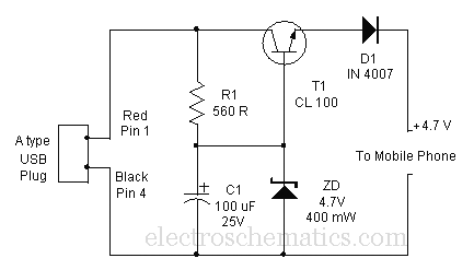
Comprehensive information about a USB cellphone charger circuit is available for learning and downloading online. The USB cellphone charger circuit is designed to convert AC mains voltage into a stable DC voltage suitable for charging mobile devices. This circuit typically...
The circuit is a battery charging system powered by Q2, Q6, R8, and D10, which provides constant current to charge the battery. When an external power supply is present, the charging current flows through R8 and D10 to charge...

AM radio receivers demodulate amplitude-modulated (AM) signals. The primary source of these signals is the Standard AM Radio Broadcast Band, although shortwave stations also utilize AM modulation. Amplitude modulation was developed between 1900 and 1917 by amateur radio enthusiasts....
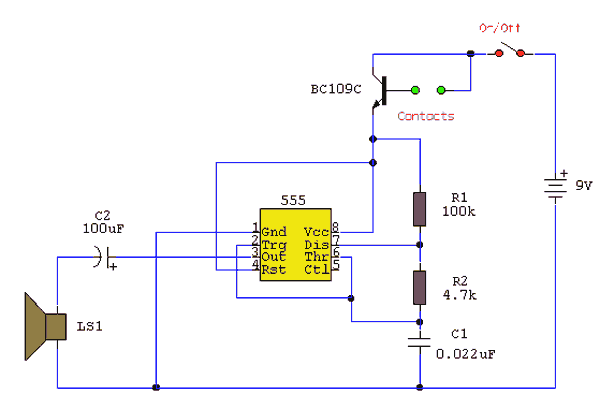
Under dry conditions, the transistor will not have any bias current and will be completely off. However, when the probes become wet, the transistor will conduct, triggering the alarm. An On/Off switch is included, and it is important to...
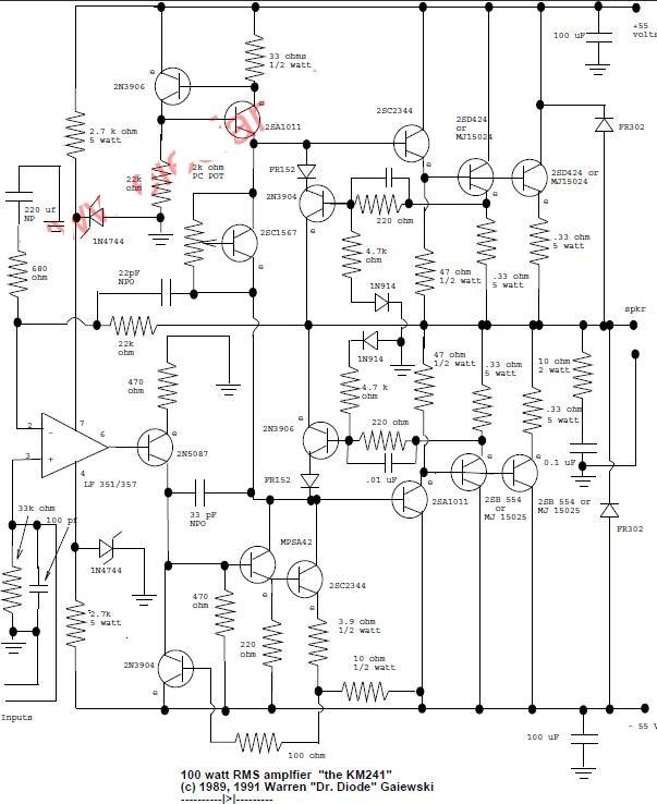
This is a 100-watt basic power amplifier designed to be relatively easy to build at a reasonable cost. It offers better performance, or musical quality, than the standard STK module amplifiers commonly found in mass-market stereo receivers. The design...