
Smoke alarm circuit

The circuit utilizes the MQK-2 gas sensor, known for its sensitivity to various combustible gases, including methane, propane, and smoke. The sensor operates by changing its inter-electrode resistance based on the concentration of gas present in the environment. In a typical configuration, the MQK-2 is connected to a voltage divider composed of resistors R1 and Rp2, which helps convert the change in resistance into a measurable voltage at node C.
The critical threshold for activating the alarm is set at one-third of the supply voltage (Vcc). This threshold is established to ensure that the circuit responds promptly to the presence of hazardous gases. When the gas concentration increases, the resistance BL drops, leading to a decrease in the voltage at node C. Once this voltage falls below the defined threshold, the operational amplifier or comparator IC1 recognizes this condition and changes its output state to low, effectively signaling the alarm system to deactivate.
Additional components may be included in the circuit for stabilization and noise filtering, such as capacitors across the power supply lines or additional resistors to fine-tune the sensitivity of the gas detection. The circuit design may also incorporate a hysteresis feature to prevent false alarms due to transient gas concentrations, ensuring reliable operation in varying environmental conditions.
Overall, the circuit serves as an effective gas detection system, utilizing the properties of the MQK-2 sensor and a simple resistor network to monitor air quality and enhance safety by providing timely alerts in the presence of combustible gases.Circuit works: When the gas sensor MQK-2 surface adsorption or smoke when combustible gas, which inter-electrode resistance BL plummeted, this time by the Rp2, R1 and BL electric poles between resistance partial pressure node C potential drop, when it fell to the potential after less than 1/3 Vcc only flip IC1 output low to stop the alarm.
Related Circuits

A LAN tester circuit diagram is presented in two designs. The first design utilizes a timer IC 555 and a decade counter 4017. The second design employs a microcontroller ATtiny2313. The first design of the LAN tester circuit incorporates the...

This circuit is a sound generator designed to create a super siren alarm signal using a live frequency generator circuit that incorporates an operational amplifier (op-amp). The circuit operates on the principle that when switch S1 is not pressed,...
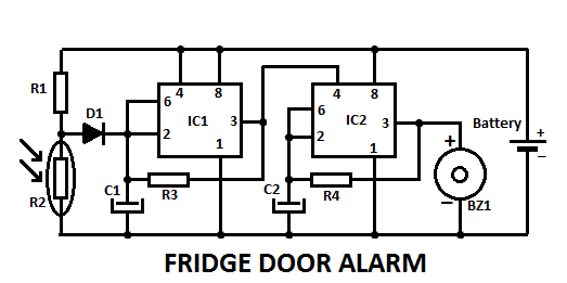
This fridge door alarm operates using a 3V battery supply and should be placed in a small box inside the fridge, near the lamp or close to the opening. The fridge door alarm circuit is designed to alert users...

The timing circuit utilizes the 556 dual time base circuit, which includes an intermediate access N8281 crossover network. This design does not require a large volume capacitor, allowing for extended time delays. Initially, the first half of the 556...
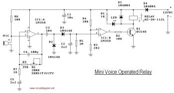
This circuit diagram illustrates a voice-operated relay, which functions similarly to a sound-activated switch circuit. It activates and deactivates the switch based on sound input. The output switch of this circuit is controlled by a relay. The release time...

The circuit diagram of an IC Controlled Emergency Light with Charger, also known as a 12V to 220V AC inverter circuit, is presented here. This circuit features automatic activation of the light during mains failure and includes a battery...