
Fridge Door Alarm Circuit

The fridge door alarm circuit is designed to alert users when the refrigerator door is left open for an extended period. The core components of the circuit typically include a microcontroller or a simple logic circuit, a battery power supply, a sensor (often a magnetic reed switch or a tilt sensor), and an audible alarm (such as a piezo buzzer).
The microcontroller or logic circuit is powered by a 3V battery, which is housed in a compact enclosure. This enclosure should be insulated to prevent moisture ingress, ensuring the longevity and reliability of the circuit. The sensor is strategically placed near the door, where it can detect the position of the door when it is closed. When the door opens, the sensor triggers the microcontroller, which initiates the alarm sequence.
The alarm system can be designed to emit a sound after a predefined delay to prevent false alarms from brief openings. The delay can be adjusted based on user preference. The audible alarm is typically a piezoelectric buzzer that produces a loud sound to alert users in case the door is left ajar.
For optimal performance, the circuit can include a low-power sleep mode to conserve battery life when the fridge door is closed. Additionally, a visual indicator, such as an LED, may be incorporated to provide a visual cue when the door is open, enhancing user awareness.
Overall, the fridge door alarm circuit is a practical solution for preventing food spoilage and energy waste, ensuring that the refrigerator operates efficiently.This fridge door alarm is using a 3V battery supply should be placed (in a small box) in the fridge near the lamp or close to the opening. With the door cl.. 🔗 External reference
Related Circuits
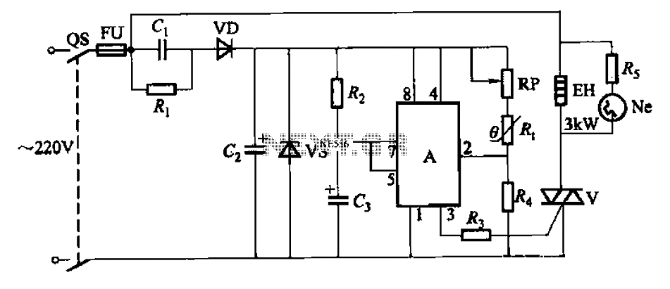
An automatic temperature control circuit is designed for climate control thermostats. Its primary function is to maintain a constant internal temperature using an electric heater (EH). The control mechanism utilizes a negative temperature coefficient thermistor as the temperature sensing...

D1 (Schottky diode) and C2 form a rectifier to create DC voltage from the Joule Thief. A Zener diode D2 is included to limit the voltage to 5.1V, preventing damage to the microcontroller, which has a maximum voltage tolerance...

Figure 1 consists of a Programmable Unijunction Transistor (PUT) and an automatic interval timer circuit. In this circuit, the PUT serves as the oscillator. The switch S1 is used to toggle between interval timing and automatic timing modes. When...

The circuit diagram features two LT1398 operational amplifiers from Linear Technology, which are utilized to generate buffered color-difference signals from RGB (red-green-blue) inputs. The red (R) input is received through a 75-ohm coaxial cable and is directed to the...
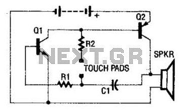
The circuit employs a two-transistor direct-coupled oscillator, with its frequency determined by capacitor C1, resistor R2, and the skin resistance across the touch pads. Since C1 and R2 are fixed values, only the skin resistance can vary the sound...
For bikers or scooter riders, it is common to forget to cancel flashing indicators after making a turn, especially without an audible reminder. Continuously checking indicator lamps is impractical, as attention should remain focused on the road. The circuit...