
Smoke-detector

The circuit's design incorporates a voltage divider formed by resistors R6 and R7, which plays a critical role in monitoring the battery's state. When the battery voltage is adequate, Q2 and Q1 remain in an active state, allowing the circuit to function normally. However, if the voltage drops below the designated level, the voltage divider output signals Q2 to turn off, subsequently leading to the deactivation of Q1. This feature is crucial for ensuring that the smoke detector does not operate under insufficient power conditions, which could compromise its functionality.
The smoke detection mechanism is integrated into the circuit through a dedicated chamber that senses smoke particles. When smoke is detected, this chamber generates a signal that turns off Q1, effectively silencing the alarm system until the smoke is cleared. This dual functionality ensures that the device can respond appropriately to both smoke and battery conditions, enhancing its reliability.
The triggering of SCR D1 by Q1 and Q3 is pivotal for the alarm sound generation. SCR D1 acts as a switch that allows a higher current to flow through the alarm sounder, producing an audible alarm in response to smoke detection or low battery status. The feedback provided by capacitor C1 is essential for creating an intermittent alarm sound, which serves to alert users without causing continuous disturbance. The distinct activation rates of the smoke detection and low battery alarms allow users to differentiate between the two conditions, thus facilitating appropriate responses.
In summary, this circuit exemplifies a robust design for a smoke detector that not only alerts users to the presence of smoke but also monitors battery health, ensuring reliable operation and safety.This circuit comes from U.S. Patent 3, 778,800, granted to BRK Electronics in Aurora, IL. The circuit provides a smoke detector with an alarm for both smoke and low batteries. The R6/R7 voltage divider monitors the battery and will turn Q2 and Ql off when the battery voltage falls too low. The smoke-detector chamber will also cut Ql off when it senses smoke. Ql via Q3, triggers SCR Dl and sounds the alarm. Capacitor Cl provides feedback that causes the alarm to sound intermittently. The smoke detector and low-battery circuits sound the alarm at two different rates.
Related Circuits
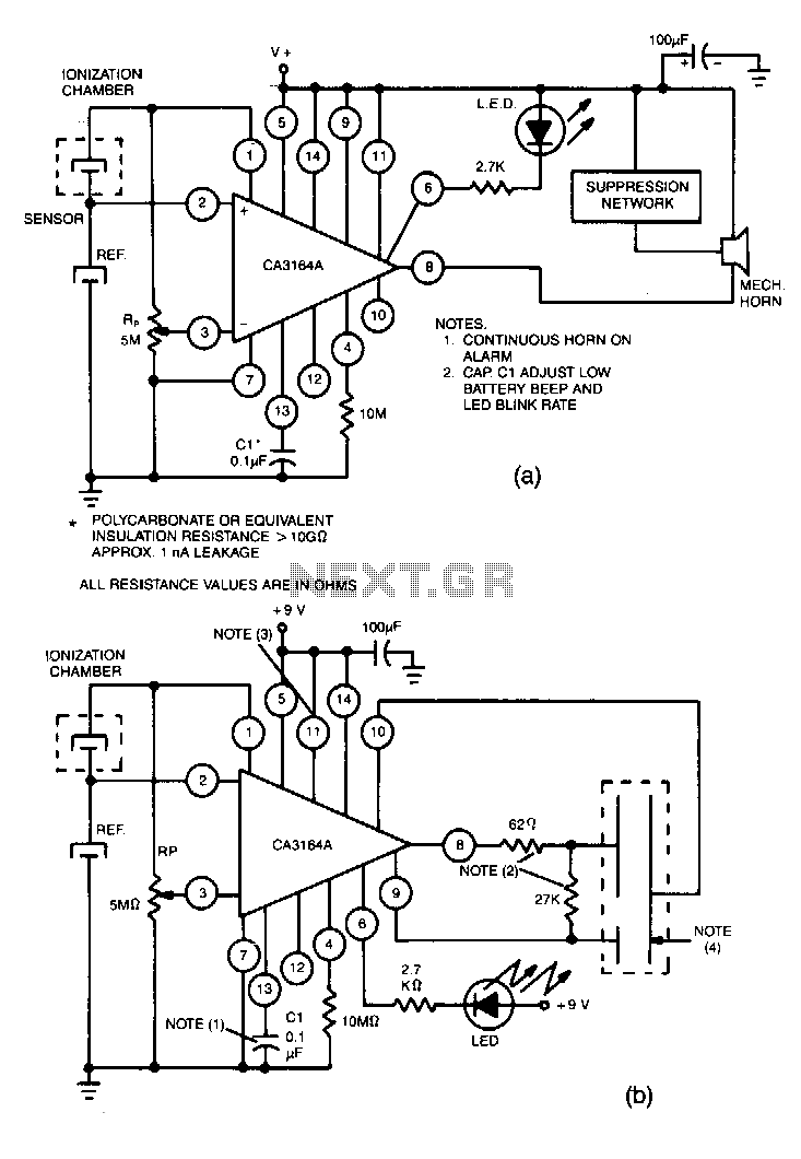
Utilize the CA3164A BiMOS detector/alarm system for operation as a smoke detector with an electromechanical horn (refer to Fig. 40-la). The output driver at terminal 8 is employed, utilizing a large npn transistor Q3 with an active pull-up, while...
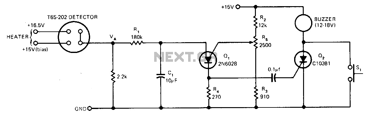
The sensor operates based on the selective absorption of hydrocarbons by an n-type metal-oxide surface. The device features a heater designed to eliminate hydrocarbons once smoke or gas is no longer detected in the immediate vicinity, allowing for reuse....
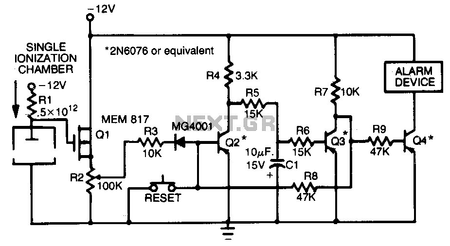
This smoke detector employs a MEM 817 p-channel enhancement mode MOSFET as its buffer amplifier. The sensor operates on the principle that the current decreases when smoke enters the chamber, leading to a negative voltage change at the gate...
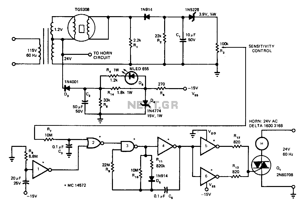
In the presence of smoke or gas, the AC output voltage increases and becomes rectified, filtered, and Zener-diode coupled (D2 for thresholding) to sensitivity control R3. Under no gas condition, the output is approximately 0 V (high). When gas...