
SMPSU With A Relay

Switched mode power supply units (SMPSUs) are widely utilized in various electronic applications due to their efficiency and compact size. They operate by converting electrical power from one form to another, typically from an AC source to a regulated DC output. The fundamental principle behind SMPSUs is the use of high-frequency switching to control the energy transfer, which significantly reduces energy loss compared to linear power supplies.
The design of an SMPS consists of several key components: a power switch (typically a transistor), a transformer, a rectifier, and a control circuit. The power switch alternates between on and off states, allowing energy to be stored in the magnetic field of the transformer during the 'on' state and released during the 'off' state. This switching action is controlled by a feedback loop that monitors the output voltage and adjusts the duty cycle of the switch to maintain a stable output.
The transformer in an SMPS is crucial, as it not only provides voltage transformation but also electrical isolation between the input and output. The rectifier converts the alternating current generated by the transformer back into direct current, which can then be smoothed using capacitors to provide a stable output voltage.
Understanding the design principles of SMPSUs involves grasping concepts such as duty cycle, switching frequency, and the role of feedback in regulation. The complexity of these systems can make them challenging to design and troubleshoot, but their advantages in terms of efficiency and size make them a preferred choice in modern electronic devices.
Overall, while SMPSUs are complex to construct and understand, their widespread application in consumer electronics, computer power supplies, and industrial equipment highlights their importance in the field of electronics.Switched mode power supply units (SMPSUs) are popular but difficult to build oneself as well problematic when it comes to understanding their design princ.. 🔗 External reference
Related Circuits
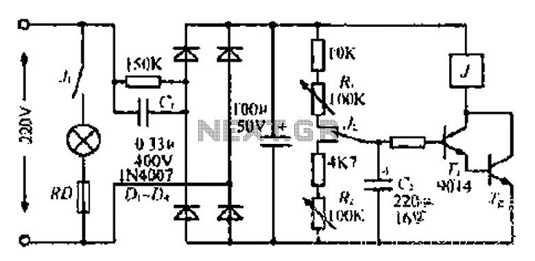
220V mains electricity is sent through a 0.33 µF capacitor (Ci) and a 50 kΩ resistive drop. A bridge rectifier composed of diodes D1 to D4 converts the AC voltage to DC. After passing through a 100 µF capacitor...
This is a simple circuit designed for an audio amplifier project to control the speaker output relay. The purpose of this circuit is to manage the delay that activates the relay, which connects the speakers to the audio amplifier....
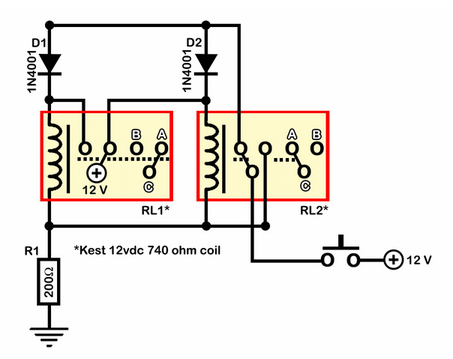
A relay circuit functions as a double-pole double-throw (DPDT) toggle, controlled by a momentary switch. The design emphasizes simplicity with minimal integration of components such as 555 timers or transistors. The circuit is depicted in an active state. Half...
This project shows you how to build a relay controller using the Basic Stamp I interfaced to the PC serial port. The Visual Basic 5 software developed for the interface lets you interact with the Basic Stamp to turn...
The two circuits demonstrate the operation of opening a relay contact shortly after the ignition or light switch is turned off. The capacitor becomes charged, and the relay remains closed until the voltage at the diode anode reaches 12...
The value may vary based on the switching frequency, environmental conditions, and required reliability level; therefore, it is advisable to verify this with the actual load. The maximum ambient temperature represents the highest temperature that can meet the coil...