
PC Relay Controller

The relay controller circuit utilizes the Basic Stamp I microcontroller, which interfaces with a PC through the serial port. The Basic Stamp I is programmed to handle commands received from the Visual Basic 5 application, which serves as the user interface for controlling the relays. The circuit can control up to two relays, allowing for the activation or deactivation of devices such as lights or motors.
The schematic consists of the Basic Stamp I connected to the PC's serial port, with the necessary connections established through a standard RS-232 interface. The Basic Stamp I's output pins are connected to the relay control inputs. Each relay is typically driven by a transistor to ensure that the microcontroller can safely control the higher current required by the relay coils.
The relay module should include flyback diodes connected in parallel with the relay coils to protect the microcontroller from voltage spikes generated when the relay is switched off. The circuit may also include resistors to limit the base current to the transistors and ensure proper operation.
Once the PC-Relay software is installed, it allows the user to select the appropriate COM port for the serial communication. The interface provides a straightforward method for sending commands to the Basic Stamp I, which in turn activates or deactivates the connected relays based on user input. This setup serves as an effective testing platform before proceeding to larger relay circuits, ensuring that all components function correctly and that the communication between the PC and the Basic Stamp I is reliable.This project shows you how to build a relay controller using the Basic Stamp I interfaced to the PC serial port. The Visual Basic 5 software developed for the interface lets you interact with the Basic Stamp to turn ON/OFF up to (2) relays attached to the Basic Stamp I/O pins.
As shown below in the screen capture of PC-Relay, it`s easy to select the desired com port using the drop-down menu. Once you have installed the PC-Relay software you`re ready to build the circuit shown above. This is a handy & quick circuit that will let you test everything before you build the bigger (relay) circuit. If everything works, i.e.. you can contr 🔗 External reference
Related Circuits

This circuit can be used to drive a 12V relay with a triggering signal of 5V. It incorporates two 1N4002 diodes, one 2N3904 transistor, and two resistors. By altering the resistor values, the input triggering voltage can be modified. The...

The relay power in the linear circuit is derived from a -120 V bias supply, while the transmit keying output from the Kenwood device is +12 V with a maximum current of 10 mA. A critical component of this...
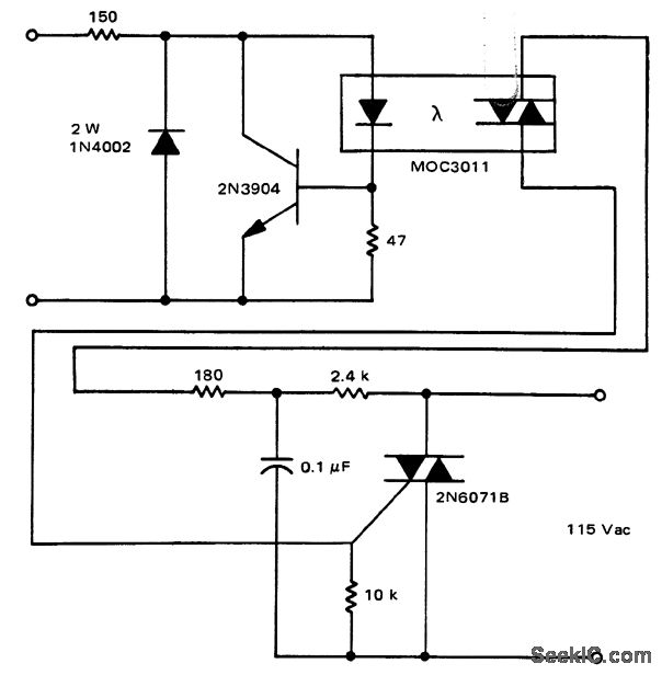
A solid-state relay circuit features an input protection mechanism utilizing the MOC3011 triac driver. The input voltage for the protection circuit can range from 3 to 30 volts DC, as noted by Motorola Semiconductor Products Inc. The solid-state relay (SSR)...
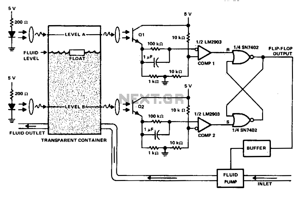
This circuit can be used to maintain fluid between two levels. Variations on this control circuit can be made to keep something that moves within certain boundary conditions. The described circuit functions primarily as a fluid level control system, designed...

Here is a simple thermostat circuit that can be used to control a relay and supply power to a small space heater through the relay contacts. The relay contacts should be rated above the current requirements for the heater....

If the control circuit of this motor driver is based on a microcontroller or digital component, it is advisable to implement a buffer for each port that controls the stepper motor driver. This precaution helps prevent overloading the microcontroller...