
soft start circuit

The soft start circuit is designed to gradually increase the power supplied to a load, thereby minimizing inrush current and reducing stress on components. The circuit typically consists of a power source, a main load, a resistor or thermistor for initial current limiting, and a control mechanism, often implemented using a relay or a transistor.
In operation, when power is first applied, the current flows through the resistor or thermistor, which limits the current and allows for a gradual increase in voltage across the load. This component can be selected based on the desired time constant for the soft start process. As the temperature of the thermistor increases or as the voltage across the resistor rises, the resistance decreases, allowing more current to flow to the load.
The control mechanism is activated after a predetermined time or voltage level is reached. This can be achieved using a timer circuit or a microcontroller that monitors the voltage across the load. Once the soft start period is complete, a relay or a transistor is triggered to bypass the resistor or thermistor, allowing full power to be supplied to the load.
In summary, this soft start circuit effectively reduces inrush current and prolongs the life of the connected components, making it suitable for applications such as motors, power amplifiers, or any other devices sensitive to sudden power changes. Proper selection of the resistor or thermistor, as well as the control mechanism, is critical to achieving the desired performance and reliability of the circuit.Hi All, I have been trying to come up with a simple soft start circuit that routes power initially through a resistor or thermistor and then activates .. 🔗 External reference
Related Circuits
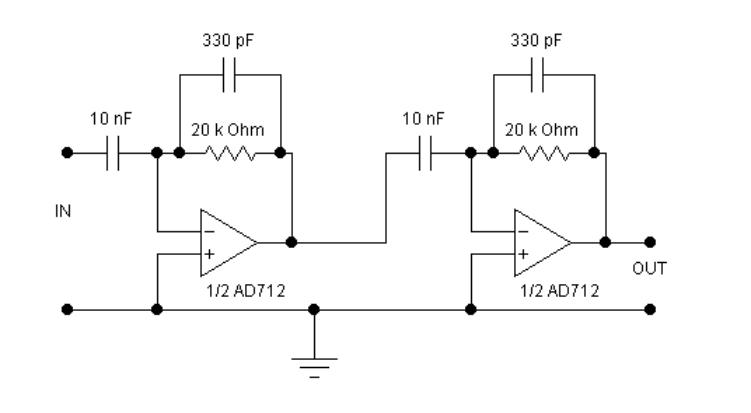
The circuits examined thus far rely on linear feedback for their operation. The magnitude of the signal returned to the negative input is always strictly proportional to the output voltage. Consequently, within the limits defined by the operational amplifier...
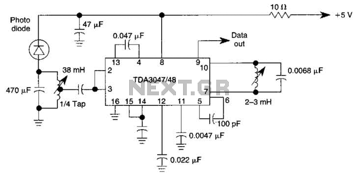
The circuit operates from a 5-V supply and has a current consumption of 2 mA. The output functions as a current source that can drive or suppress a current exceeding 75 mA with a voltage swing of 4.5 V....
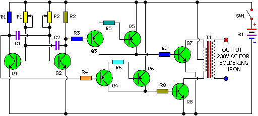
This is a simple and cost-effective inverter designed for small soldering irons (25W, 35W, etc.) to be used in the absence of mains supply. The circuit employs eight transistors along with a few resistors and capacitors. Transistors Q1 and...
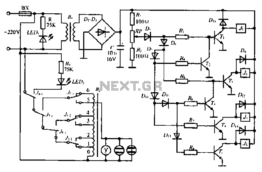
A step-down transformer converts AC 220V to a lower voltage. A diode bridge rectifier and filter capacitor provide a direct current (DC) output, which fluctuates with variations in the grid voltage. A resistive voltage divider is used for sampling....
The Adjustable Timer circuit initiates timing upon activation. A green LED illuminates to indicate that timing is in progress. Once the designated time period elapses, the green LED turns off, the red LED activates, and an audible bleeper sounds....
The IRF820 MOSFET has a voltage rating of 500V; it should work well in preamp stages of most tube amps. The 100-ohm resistor is there to suppress H.F. oscillations. If the IRF820 is physically close to the 12AX7 plate,...