Adjustable Timer circuit 1-10 minute

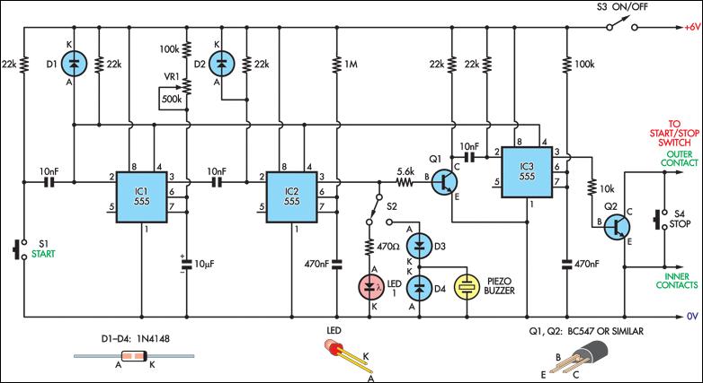
The Adjustable Timer circuit initiates timing upon activation. A green LED illuminates to indicate that timing is in progress. Once the designated time period elapses, the green LED turns off, the red LED activates, and an audible bleeper sounds. The duration of the time period is adjustable.
The Adjustable Timer circuit is designed to provide a visual and audible indication of elapsed time. It typically consists of a microcontroller or timer IC, a resistor-capacitor (RC) timing network, two light-emitting diodes (LEDs), and a sound-generating component such as a piezo buzzer.
The circuit operates by first charging a capacitor through a resistor, which defines the time period. The microcontroller monitors the voltage across the capacitor and determines when it has reached a predefined threshold, indicating that the time period has expired. At this point, the microcontroller deactivates the green LED and activates the red LED and the bleeper, signaling the end of the timing cycle.
The adjustable feature of the timer may be implemented using a potentiometer in the RC timing network, allowing the user to set the desired time period. The circuit may also include a reset button to restart the timing process at any point.
In application, this circuit is suitable for various timing tasks, such as cooking timers, reminders, or other countdown applications where visual and audible alerts are beneficial. Proper design considerations should be made for component selection to ensure reliability and accuracy in timing operations.The Adjustable Timer circuit starts timing when switched on. The green LED lights to show that timing is in progress. When the time period is over the green LED turns off, the red LED turns on and the bleeper sounds. The time period is set.. 🔗 External reference


