
Soft Start PSU

The circuit comprises two separate soft start power supply modules designed to gradually ramp up the output voltage to a predetermined level, thereby minimizing inrush current and preventing potential damage to connected loads. Each power supply module can be independently configured to meet specific voltage and current requirements.
The soft start feature is typically implemented using a combination of an operational amplifier (op-amp), a resistor-capacitor (RC) timing network, and a transistor or MOSFET for output control. The RC network is responsible for controlling the time constant of the voltage ramp-up, allowing for a smooth increase in output voltage. The op-amp monitors the output voltage and adjusts the control signal to the transistor or MOSFET accordingly.
In operation, upon powering the circuit, the capacitor in the RC network begins to charge, causing the voltage at the op-amp input to rise gradually. As this voltage crosses a certain threshold, the op-amp activates the transistor or MOSFET, allowing current to flow to the load. The rate of voltage increase can be adjusted by selecting appropriate resistor and capacitor values in the RC network.
The two modules can be synchronized or operated independently based on the design requirements. Additional features may include over-voltage protection, under-voltage lockout, and thermal shutdown to enhance reliability and safety. The output voltage can be monitored using feedback mechanisms to ensure stability and accuracy during operation.
This design is particularly useful in applications where sensitive electronic components are used, as it reduces the risk of damage due to sudden surges in voltage.Two soft start power supplies. The output voltage slowly increases to the desired output 🔗 External reference
Related Circuits
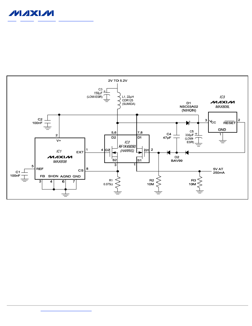
To ensure a full-load start-up, the additional circuitry in this regulated boost converter disconnects the load until the output voltage reaches regulation. Proper operation necessitates a gate-drive voltage adequate to maintain low on-resistance in the switching MOSFET; however, during...
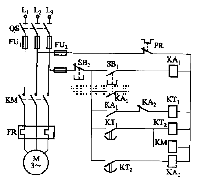
The circuit illustrated in Figure 3-76 employs two time relays, KTi and KTz, to manage the operation and downtime of a motor. The circuit utilizes two time relays to provide precise control over the motor's operational cycles. Relay KTi is...

Oscillators that generate a predetermined number of pulses are often required in applications such as video work. This oscillator starts 13 ms after the control signal goes high and stops immediately when the input signal goes low. In electronic applications,...

This Arduino-based project involves constructing a lamp with various light displays, including a color sequencer, dimming light, color chaser, and firelight, all controlled by a touch bar on the circuit board. The design adopts a minimalist approach, incorporating only...
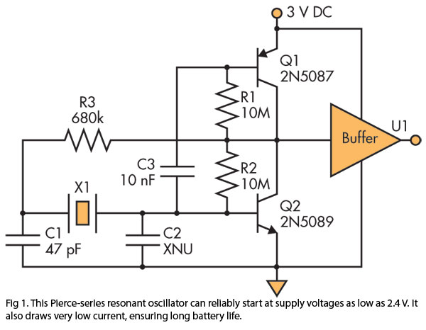
A Pierce (crystal) oscillator designed to deliver a stable clock signal for a minimum duration of one year when powered by battery voltages as low as 2.4 V. The Pierce oscillator circuit is a type of crystal oscillator that utilizes...
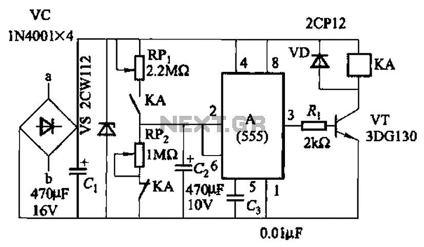
The circuit, as illustrated in Figure 3-82, employs a 555 IC to control a motor automatically, managing its start and stop cycles. The running and stopping times of the motor can be adjusted by modifying the values of potentiometers...