
Solar Cell Voltage Regulator

This comparator circuit is designed to provide a straightforward solution for monitoring voltage levels in a solar power system. The primary function is to indicate whether the voltage output from the solar cells is above or below a predetermined threshold. The circuit operates by utilizing a 5V voltage regulator, which stabilizes the voltage supplied to the circuit components. The choice of the low-dropout 4805 voltage regulator is optimal as it allows the circuit to function effectively even with minimal input voltage, which is common in solar applications.
The transistors, T1 and T2, serve as the core switching elements. The PNP transistor (T1) is activated when the voltage exceeds the set threshold, while the NPN transistor (T2) operates in the opposite condition. This complementary configuration allows for efficient control of the LEDs, which serve as visual indicators. When the voltage is adequate, one LED may illuminate, indicating a "just right" status, whereas the other LED may light up when the voltage drops below the acceptable level, signaling a "too low" condition.
The resistors in the circuit are crucial for setting the appropriate biasing conditions for the transistors and determining the LED current, ensuring they operate within safe limits without burning out. Capacitors are included to filter out any noise and stabilize the voltage supply, enhancing the reliability of the circuit's performance in varying environmental conditions.
The power supply for this circuit can be flexible, accommodating various battery configurations. A 4V battery is specified, but alternatives such as three alkaline batteries (4.5V) or three NiCd cells (3.6V) are also viable options. This flexibility ensures compatibility with different solar cell setups, which may have varying output voltages depending on their size and arrangement.
Overall, this simple comparator circuit is an effective solution for monitoring solar cell output, providing essential feedback for users to ensure optimal performance of their solar power systems.This device is designed to be a simple, inexpensive comparator`, intended for use in a solar cell power supply setup where a quick too low` or just right` voltage indicator is needed. The circuit consists only of one 5V regulator, two transistors, two LEDs, five resistors, two capacitors, and one small battery.
Although a 4-V battery is indicated, 4. 5 V (3 alkalines in series) or 3. 6 V (3 NiCd cells in series) will also work. The specifications of voltage regulator IC1 are mainly determined by the size and number of the solar cells and the current pull of the equipment connected to the output. Here the low-drop 4805 is suggested but other regulators may work equally well as long as you observe the output voltage of the solar cells.
Transistors T1 and T2 are complementary types i. e. one each of the pnp and npn variety. 🔗 External reference
Related Circuits
A low voltage reference is essential for providing an offset source or biasing, or simply serving as a reference for a comparator. Its adjustable feature should be compatible with this circuit. A low voltage reference circuit is designed to deliver...
This article presents a high reliability 1200V High Voltage Integrated Circuit (1200V HVIC) for half bridge driver applications, aimed at reducing the IC's supply current by approximately 50%. The 1200V High Voltage Integrated Circuit (HVIC) is designed specifically for half-bridge...
This is a simple NiCd battery charger powered by solar cells. A solar cell panel or an array of solar cells can charge a battery at more than 80% efficiency. The described circuit functions as a basic NiCd battery charger...
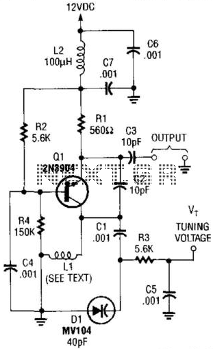
This VHF VCO circuit operates within the frequency range of 30 to 200 MHz. Q1 may be substituted with a 2N3563 for frequencies exceeding 100 MHz. The inductor, L1, is selected to resonate at the desired frequency in conjunction...
One of the drawbacks of a three-pin voltage regulator is that the input voltage needs to be 2.5 to 3 V higher than the output voltage. This makes these integrated regulators unsuitable for battery power supplies. For instance, if...

The audio mixer schematic proposed is developed around four amplifiers built inside the SSM2024 produced by Precision Monolithics Inc. (PMI) and is voltage-controlled (VR). The maximum VR voltage is 5.5 volts. The signal-to-noise ratio is 90 dB, and the...