
Voltage-Tuned Vhf Oscillator

This VHF Voltage-Controlled Oscillator (VCO) circuit is designed to generate frequencies in the Very High Frequency (VHF) range, specifically from 30 MHz to 200 MHz. The core component, Q1, is a transistor that can be replaced with a 2N3563 for applications requiring operation above 100 MHz. This substitution allows for enhanced performance at higher frequencies, ensuring the circuit maintains stability and efficiency.
The inductor, L1, is a critical element in the circuit, as it is tuned to resonate with the varactor diode's capacitance. In this design, a varactor with a capacitance of 40 pF is employed, which allows for fine-tuning of the output frequency. The choice of the varactor is essential, as it directly influences the frequency modulation capabilities of the VCO. For applications demanding higher linearity in frequency response, the circuit can accommodate alternative varactor models or utilize two varactors arranged in a back-to-back configuration. This arrangement can significantly enhance the linearity of the tuning curve, making the VCO more suitable for precision applications.
To implement this VCO effectively, careful consideration must be given to the selection of passive components, including the inductor and the varactor, to ensure optimal performance across the desired frequency range. Additionally, layout considerations such as minimizing parasitic capacitance and inductance are vital for maintaining signal integrity and reducing unwanted oscillations. Overall, this VHF VCO circuit presents a versatile solution for various RF applications, including communication systems, signal generation, and frequency synthesis. This VHF VCO circuit is suitable for 30 to 200 MHz. Q1 can be replaced by a 2N3563 for operation above 100 MHz . LI is chosen to resonate to the desired frequency with the varactor capacitance of 40 pF. Other varactors can be substituted or two back-to-back varactors can be used for better linearity, depending on the application.
Related Circuits
A NE555 integrated circuit (IC) is utilized for the design of a variable low-frequency oscillator, and a schematic is provided. The NE555 timer IC is a versatile and widely used device in various electronic applications, particularly in generating precise timing...
The Colpitts oscillator circuit schematic is closely related to the shunt-fed Hartley oscillator, with the primary distinction being in the tank circuit design. In the Colpitts oscillator, two capacitors are utilized in place of divided coils. The basic feedback...
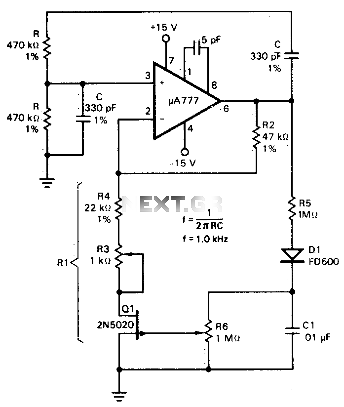
A field effect transistor (FET), designated as Q1, functions within the linear resistive region to facilitate automatic gain control. The attenuation of the RC network is one-third at the oscillation frequency with zero phase shift, necessitating that the amplifier...
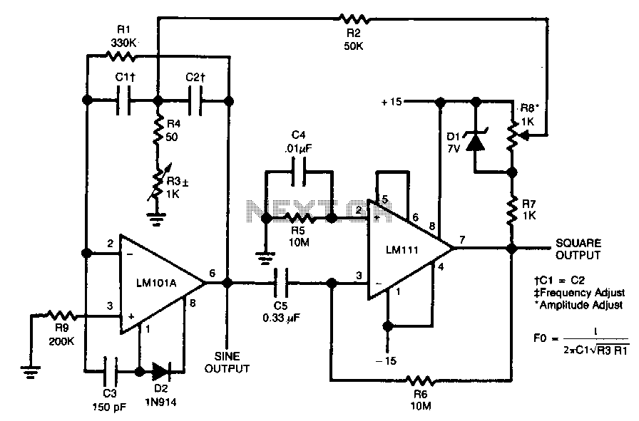
The circuit is designed to generate both sine and square wave outputs for frequencies ranging from below 20 Hz to above 20 kHz. The frequency of oscillation can be easily adjusted by modifying a single resistor, which is a...
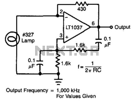
In this circuit, the Wien bridge network provides phase shift, and the lamp regulates the amplitude of the oscillations. The smooth, limiting nature of the lamp's operation, in combination with its simplicity, yields good results. Harmonic distortion is below...
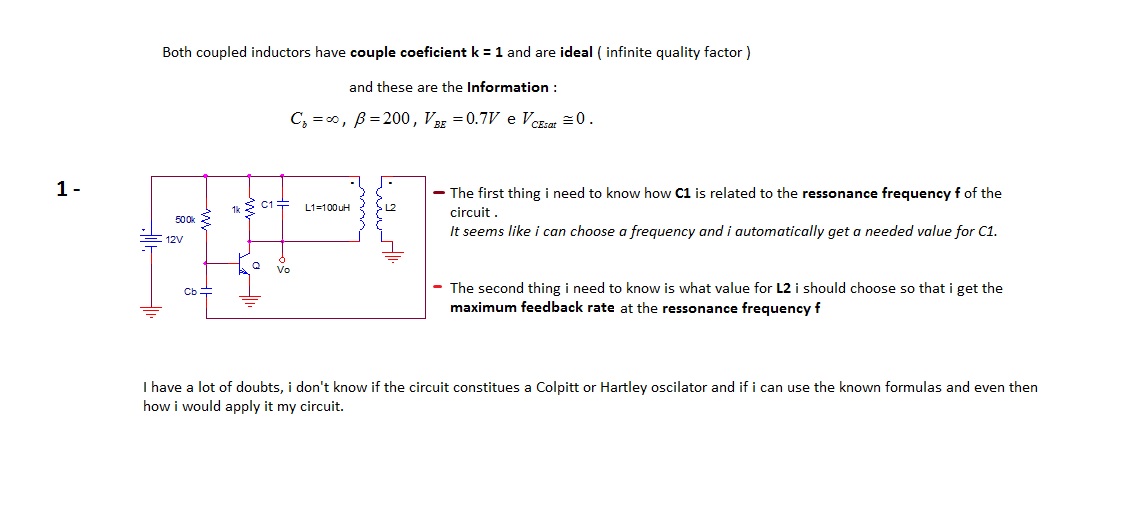
The first thing to understand is how capacitor C1 is related to the resonance frequency f of the circuit. It appears that selecting a frequency allows for the automatic determination of the necessary value for C1. There are uncertainties...