
Solar Charger Schematic

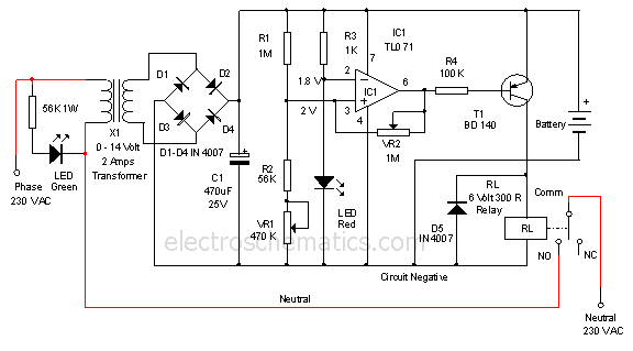
The described circuit operates as a DC to DC inverter, designed to enhance the voltage and current output from solar panels for battery charging applications. The core components include a transistor that acts as a switch, controlling the flow of current through the primary winding of the coil. The primary winding, with 45 turns, generates a magnetic field that induces a voltage in the secondary winding of 15 turns. This induced voltage is critical for feedback to the transistor's base, ensuring stable oscillation and efficient operation.
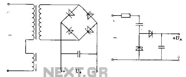
Capacitors are employed to smooth out the voltage fluctuations and stabilize the output, while the resistor helps to limit the current flowing through the circuit, protecting sensitive components from potential damage. The diode serves a crucial role in directing the current towards the battery, preventing backflow and ensuring that the battery receives the correct polarity for charging.
The design is particularly advantageous for applications such as charging motorcycle batteries or powering emergency lighting systems. During the day, solar panels harness sunlight, converting it into electrical energy, which is then stored in the battery. At night, the stored energy can be utilized for lighting, providing a sustainable and cost-effective solution for energy needs.
This circuit exemplifies a practical approach to renewable energy utilization, demonstrating how simple electronic components can be integrated to create efficient energy systems that harness solar power. The design is both scalable and adaptable, allowing for modifications based on specific energy requirements or components available, thus promoting innovation in renewable energy applications.To take advantage of sunlight shining on the earth can continue to be utilized to serve as a power source so that we can at least save on electricity prices continuing to rise, below is one of a series of simple power plant can be created and used to fill your motorcycle battery or for emergency lights. Sunlight is received by the solar panels are then processed into electricity, but electricity generated from each panel is still too small where the 8 Cell Panel arranged in series only mrnghasilkan voltage of approximately 4 volts with a current 200 mA. nah therefore required an electronic circuit to increase the voltage and current enough to be used as a Battery Charger.
Electronic Rangakain act as a series of DC to DC Inverter (DC to DC Inverter), which was built by two pieces of Capacitor, Resistor 1, a transistor, a diode, and a coil which is the point of the creation of this series. The circuit was built with a single oscillator system (blocking oscillator) which was built by the transistor and a coil in which the primary winding totaling 45 turns and 15 turns in the secondary as feedback to provide the voltage at the base of the transistor output of the primary winding connected to the diode and used to The battery charging.
When the circuit is coupled with the Emergency Neon Lights will certainly get enough voltage to light at night for free. because its batteries during the day in charge by the sun. 🔗 External reference
Related Circuits
This charger will quickly and easily charge most any lead acid battery. The charger delivers full current until the current drawn by the battery falls to 150 mA. At this time, a lower voltage is applied to finish off...
A straightforward method for charging a battery using a higher voltage source is illustrated in the accompanying circuit diagram. The circuit requires only one resistor to establish the desired charging current, which can be determined by dividing the voltage...
The pre-regulator circuit is connected to a capacitor and a resistor element. The regulator operates in its conducting direction through the input. A capacitor is connected to AC power, and in the blocking direction, it limits the current, allowing...
Savings on electricity bills can be achieved by utilizing alternative power sources. The photovoltaic module, or solar panel, described here can provide a power output of 5 watts. Under full sunlight conditions, the solar panel generates an output voltage...
This is a 12-volt lead-acid automatic battery charger that stops the charging process once the battery reaches a full charge. This feature prevents overcharging. The 12-volt lead-acid automatic battery charger is designed to efficiently charge lead-acid batteries while ensuring safety...
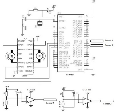
The electronic schematic of the Light Detector Robot can be divided into three main components: the sensor, the microcontroller, and the DC motor driver. The light sensor utilized in this design is a Light Dependent Resistor (LDR), which alters...