
constant current battery charger

The circuit operates by connecting a higher voltage battery in parallel with the battery to be charged. The resistor plays a crucial role in controlling the current flowing into the charging battery. To calculate the appropriate resistance value, the voltage difference between the source battery and the target battery is measured. This voltage difference is then divided by the desired charging current to obtain the resistance value using Ohm's Law (R = V/I).
For instance, if the higher voltage battery is at 12V and the battery being charged is at 6V, the voltage difference is 6V. If the desired charging current is 1A, the required resistance would be R = 6V / 1A = 6 ohms. This resistor must be rated to handle the power dissipation, which can be calculated using the formula P = I^2 * R. In this case, P = (1A)^2 * 6Ω = 6W, so a resistor rated for at least 10W would be advisable to ensure reliability and prevent overheating.
Additionally, it is essential to consider the specifications of both batteries to ensure safe charging. The charging process should be monitored to prevent overcharging, which can lead to battery damage or reduced lifespan. Implementing a diode in series with the charging circuit can prevent reverse current flow when the higher voltage battery is disconnected, thereby protecting the charged battery.
Overall, this simple charging circuit is effective for applications where a higher voltage source is available, and it can be easily modified to accommodate different voltage and current requirements by adjusting the resistor value accordingly.A simple method of charging a battery from a higher voltage battery is shown in the circuit below to the left. Only one resistor is needed to set the desired charging current and is calculated by dividing the difference in battery voltages by the charge current..
🔗 External reference
Related Circuits
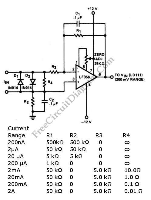
A current-to-voltage converter circuit can be constructed using a single resistor. This design is straightforward, as any current flowing through a resistor will naturally generate a voltage. A current-to-voltage converter, also known as a transimpedance amplifier, is primarily utilized to...
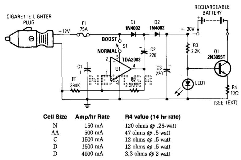
This circuit provides an output of up to 20 V from a 12-V automotive supply, enabling constant current charging of NiCad battery assemblies with a total voltage of approximately 18 V. The circuit utilizes a square-wave oscillator (VI) and...

The simplest method for measuring high AC currents is to use a clamp meter; however, these devices are typically quite costly, often starting at several hundred dollars. Add-on clamp meter adapters can be effective, but they are compatible only...
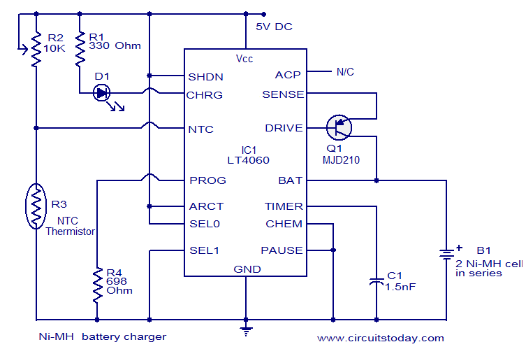
This circuit diagram represents a highly efficient Ni-MH battery charger utilizing the LT4060 integrated circuit from Linear Technologies. The circuit can also accommodate Ni-Cd batteries with minor modifications. To charge Ni-Cd batteries, the CHEM pin (pin 12) of the...
Here we use the PIC16711. Rechargeable battery capacity is rated in mAH (milliampere-hours). The total capacity of a battery is defined as "C", that is it can supply C mA for 1 hour, or 2C for 30 minutes etc....
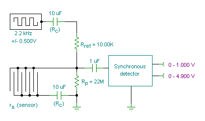
A small transmitter board interfaces with a microcontroller and conductivity probe to measure liquid conductance and conductivity. Precise equations and measurements are provided for this microcontroller-controlled conductivity meter. The described circuit consists of a compact transmitter board that serves as...