
solar led

This circuit operates based on a straightforward principle of solar energy conversion and LED illumination. The core components include a solar cell, a rechargeable battery, two diodes (D1 and D2), a PNP transistor, and two resistors (R1 and R2).
The solar cell is responsible for converting sunlight into electrical energy, which charges the battery. The choice of a solar cell must be carefully considered; it should have an output voltage that exceeds the battery voltage by at least 1.4 volts to ensure efficient charging. Diodes D1 and D2 play a critical role in preventing reverse current flow, ensuring that the battery is charged effectively while also protecting the circuit from potential damage.
The PNP transistor serves as a switch in the circuit. During daylight, when the solar cell is generating voltage, the base of the PNP transistor receives a higher voltage, effectively turning it off and preventing current from flowing to the LED. Conversely, in the absence of light, the voltage at the base drops, turning the transistor on and allowing current to flow from the battery through resistor R2 to the LED. Resistor R2 is essential for current limiting, ensuring that the LED operates within its safe current range, thereby extending its lifespan and maintaining optimal performance.
Overall, this circuit design emphasizes simplicity and efficiency, allowing for the practical implementation of solar-powered LED lighting with a minimal number of components while ensuring reliable operation across different LED color types.I developed this circuit because I kept seeing solar LED lights for sale that use a CDS light sensor and just seemed to have more components than necessary. It just seemed like it did not need to be that complicated. This circuit does not do any voltage boost that would be necessary to drive a white led from a voltage source of less than 3 volts.
If you use a 3. 8 volt cell you can drive a white led with this circuit. If you use lower voltage cell(s) you can still drive many other color LEDs (i. e. green, red, orange. ). NOTE: you must choose a solar cell(s) that is greater than your battery voltage + 1. 4 volts. The solar cell charges the battery through D2 and D1, the voltage on the base of the transistor during charging mode turns off the PNP transistor. When there is no light on the solar cell, the voltage at the D1, D2, and base goes low, when this happens current flows through the emitter/base of the PNP transistor and R1, thereby biasing the PNP transistor on.
Now current will flow from the battery through R2 and turn on the LED. R2 is used to current limit the current thorough the LED. 🔗 External reference
Related Circuits
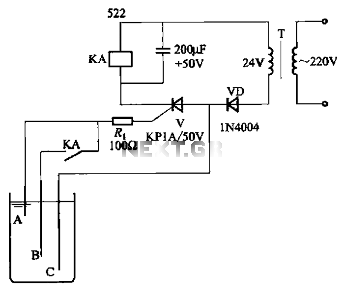
The circuit depicted in Figure 11-14 utilizes a unidirectional thyristor within liquid level automatic control systems. It incorporates electrodes that serve as sensing elements for detecting the level of water or other conductive liquids. The circuit features a current...
The TLD 5085EJ is a smart LED buck converter featuring an integrated power switch, designed to drive a load current of up to 1.8A with excellent line and load regulation. This device is specifically intended for stepping down input...

The M-88L70 is a complete DTMF receiver that combines both band-split filter and decoder functions into a single 18-pin DIP or SOIC package. It is manufactured using CMOS process technology, which allows for low power consumption (maximum 18 mW),...

The circuit illustrated briefly flashes an LED to attract attention and remains illuminated as long as power is supplied. The circuit utilizes the well-known 555 timer integrated circuit (IC) configured as a standard astable multivibrator with resistors RA, RB,...
This is a resonant mode LED driver circuit. This circuit is designed to provide a constant DC current through a specified number of LEDs. The resonant mode LED driver circuit operates by utilizing resonant inductive elements to achieve efficient energy...
The optically-controlled circuit plays a crucial role in urban street lighting and corridor illumination. By utilizing this circuit, lighting lamps can be automatically turned on and off based on ambient light levels, thereby reducing the need for manual control,...