
Level one thyristor-controlled circuit sink type b

The circuit operates by employing a thyristor, which is a semiconductor device that acts as a switch, allowing current to flow only when triggered by a gate signal. In this application, the thyristor is used to control the flow of current based on the liquid level detected by the electrodes. When the liquid level reaches a certain point, the electrodes become conductive, triggering the thyristor and allowing current to pass through.
The inclusion of a current limiting resistor (Ri) is critical for the protection of the thyristor. This resistor ensures that the gate current does not exceed the maximum ratings specified by the manufacturer, thus preventing thermal runaway and potential failure of the thyristor. The value of Ri must be carefully calculated based on the supply voltage and the required gate current for the thyristor to operate effectively.
In practical applications, this circuit can be utilized in various liquid level control systems, such as water tanks, chemical storage, and other applications where monitoring and controlling liquid levels is essential. The design can be expanded to include additional features, such as alarm systems or automatic pumps, to enhance the functionality of the liquid level control system. Overall, the integration of a thyristor and a current limiting resistor in this circuit provides an efficient and reliable solution for automatic liquid level control. Circuit shown in Figure 11-14. It uses a one-way thyristor, is poured into the liquid level automatic control circuits. Electrodes for detecting sensing element for water or ot her conductive liquid level control. Figure, Ri current limiting resistor to limit the flow of current through the thyristor gate, so as not to burn the tubes.
Related Circuits
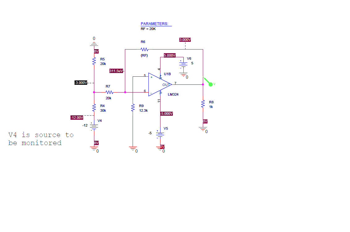
The UCD90124/A is utilized to monitor multiple voltages, some of which exceed 2.5V. Scaling circuits are implemented to prevent exceeding the 2.5V maximum on the MON inputs. The inquiry pertains to whether raw voltage values or scaled values should...
This simple circuit tests speakers, microphones, transformers, and voltage. It is essentially a very low-frequency oscillator that produces extremely short pulses. The sound produced is easy to hear and helps determine the precise direction it originates from, making it...
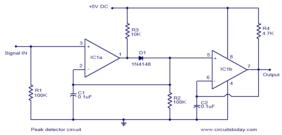
LM339-based peak detector circuit. Simple and easy to construct. Operates from a 5V DC single supply. LM339 is a dual comparator. The LM339-based peak detector circuit is designed to capture and hold the peak value of an input signal. This...
The following circuit illustrates the use of the AD8531 integrated circuit for the automatic control of LCD panel backlighting. Features include the ability to compensate for aging effects. The AD8531 is a precision operational amplifier that is well-suited for applications...
Long-distance infrared transmitter circuit diagram. This simple circuit offers a considerable range by utilizing three infrared transmitting LEDs (IR1 through IR3) in series to enhance the radiated power. To further improve directivity and power density, the IR LEDs can...
Over-Temperature Alarm Circuit Uses Common, Inexpensive Components | Negative-temperature-coefficient (NTC) thermistor, ICs. The Over-Temperature Alarm Circuit is designed to detect excessive temperatures and provide an alert using readily available and cost-effective components. The core sensing element of this circuit is...