
Solar Panel AC Mains Relay Changeover Circuit

The automatic changeover relay circuit described operates by seamlessly switching between two power sources to ensure consistent battery charging. The circuit is primarily composed of an operational amplifier (IC 741), which is used to monitor the voltage levels from the solar panel. The operational amplifier serves as a comparator, determining when the solar panel output is insufficient for charging the battery.
The central component of the circuit is the LM317 voltage regulator, which is configured to maintain a constant output voltage of 7 volts. This output is critical for charging the 6V battery efficiently. The LM317 is connected in such a way that it can provide a steady current, crucial for the longevity and performance of the battery.
When the solar panel output falls below the threshold of 7 volts, the relay is activated, disconnecting the solar panel and connecting the AC/DC adapter to the LM317. This transition is essential for maintaining battery charge during periods of low solar energy, such as at night or during cloudy weather. The AC/DC adapter ensures that the battery continues to receive power, preventing discharge and maintaining its charge state.
The relay used in the circuit is typically a double-pole double-throw (DPDT) type, which allows for the switching of both the solar panel and the AC adapter connections. This design ensures that only one power source is connected to the battery at any given time, preventing potential damage from simultaneous connections.
Overall, the automatic changeover relay circuit effectively combines renewable energy input with traditional power sources, providing a reliable solution for battery charging in various conditions. The integration of these components ensures that the system is efficient, responsive, and capable of maintaining battery health over extended periods.The discussed automatic change over relay circuit was requested by Mr. Karimulla Baig. The circuit normally charges the connected battery at constant current through the power received from the solar panel, andrevertsto DC power from an AC/DC adapter in the absence of solar energy (during night time). Lets the read the request in more details: i ha ve made the both chargers of both AC mains charger and solar Charger and i need a change over for this kindly help me in designing the change over circuit. Looking at the proposed circuit diagram, we see three basic stages, on the left an IC 741 circuit, at the center a voltage regulator stage using IC LM317, while on the top an AC/DC adapter circuit.
The IC317 circuit is a regulator circuit, configured for generating aconstantcurrent, 7 volts output to the 6V battery which is connected at the given points. However, the moment the panel voltage drops below 7 volts, the relay switches OFF, connecting the DC adapter power with the regulator circuit, and now the batterystartsgetting charged through the AC/DC adapter voltage source.
🔗 External reference
Related Circuits
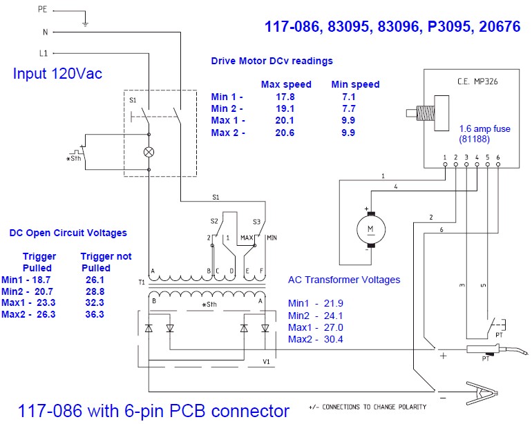
The wire speed DC motor consistently receives approximately 20 volts, irrespective of the switch position on the nozzle handle. The switch has been tested with an ohmmeter and functions properly. Even after disconnecting the switch from the circuit board,...
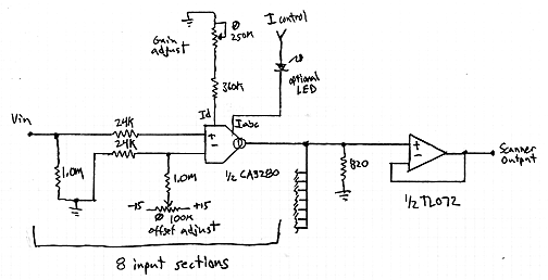
This design is for an interpolating scanner, a circuit featuring multiple signal inputs, a control voltage input, and a signal output. The output selectively transitions between inputs, smoothly fading from one to the next as the control voltage increases....

The circuit of the easy-to-use LM3sDZ temperature detection system does not provide an adjusted output to obtain a 1 (hnV/°C) temperature change range if the temperature is between 0°C and a specified limit. The output voltage ranges from 0...
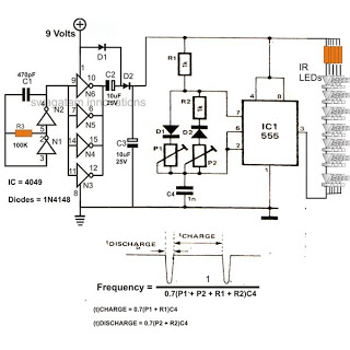
The 4049 section serves as a fundamental voltage doubler circuit, enhancing a 9 V supply to approximately 15 V. This elevated voltage subsequently acts as the supply voltage for the following 555 pulse modulator section. A key characteristic of...
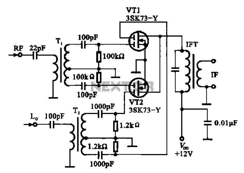
A balanced mixer circuit is illustrated using two dual-gate field effect transistors (FETs). The RF signal is coupled to the gates of these transistors through an input signal transformer (T1). Additionally, a local oscillation signal is introduced to the...
This circuit produces the famous Big Ben sound. It produces the "ding dong" sound when switched ON. Basically, the circuit alternates between two frequencies which are adjustable. This produces the "ding-dong" sound. The first IC (left) oscillates at about...