
Big Ben Sound circuit

The first IC determines how fast the changeover from one frequency to the other takes place and the second IC determines the tone of the final output. By varying the VR1, the changeover rate can be adjusted. By varying VR2 the tone can be adjusted.
The circuit is designed to emulate the iconic sound of Big Ben, utilizing two integrated circuits (ICs) to create the characteristic "ding-dong" effect. The first IC serves as an oscillator, generating a square wave at approximately 1Hz. This frequency can be fine-tuned using a variable resistor (VR1), allowing for adjustments in the timing of the sound's changeover from one tone to another.
The output from the first IC is fed into the second IC, which is responsible for generating the distinct tones of the "ding" and "dong." The modulation of this tone is achieved by varying the voltage signal received from the first IC. A second variable resistor (VR2) is incorporated into the circuit to allow for further adjustments to the tone's pitch, providing flexibility in sound output.
The circuit can be powered with a standard DC supply, and appropriate decoupling capacitors should be included to filter any noise that may affect the performance of the ICs. Additionally, a speaker or piezo buzzer can be connected to the output of the second IC to reproduce the sound. The design can be housed in a suitable enclosure to protect the components and enhance the aesthetic appeal, ensuring that the circuit remains functional and reliable over time.This circuit produces the famous Big Ben sound. It produces the "ding dong" sound when switched ON. Basically the circuit alternates between two frequencies which are adjustable. This produces the "ding-dong" sound. The first IC(left) oscillates at about 1Hz. The second IC's tone is modulated by the changing voltage at the output of the first IC. The first IC determines how fast the changeover from one frequency to the other takes place and second IC determines the tone of the final output. By varying the VR1, the changeover rate can be adjusted. By varying VR2 the tone can be adjusted. 🔗 External reference
Related Circuits
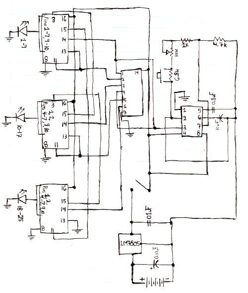
Here is the schematic for the circuit. Solder all the components onto a perfboard. The drawings may not be very clear. Essentially, the 555 timer generates a pulse. The circuit utilizes a 555 timer IC configured in astable mode, which...

A simple battery charger designed for Nickel Metal Hydride batteries that require current-regulated charging. The charger delivers a charging current of 140 mA for efficient battery charging. The power supply section includes a 0-18 volt AC 1 Ampere step-down...
Capacitors C1 and C2, in conjunction with a speed controller, function by receiving voltage at the gate of the MOSFET. When the voltage on C is applied, it activates the operation of the MOSFET. In this circuit configuration, capacitors C1...
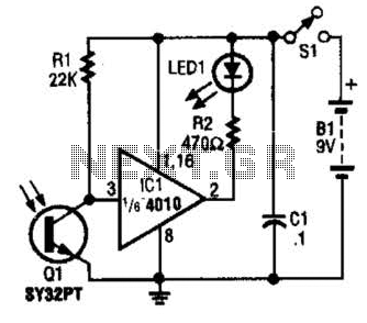
The IR Tester circuit indicates whether the button pressed on a remote control is functioning. Q1 is a phototransistor that is activated by infrared (IR) energy. The IR Tester circuit operates by detecting infrared signals emitted by remote control devices...
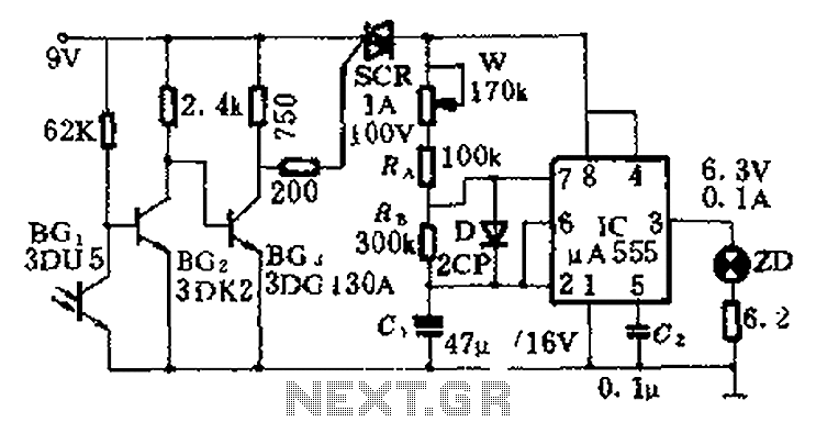
This circuit is designed for nighttime illumination and corridor lighting. During daylight, sufficient light causes BG3 to conduct, preventing the SCR from oscillating. As a result, the circuit remains inactive, and the light does not turn on. At night,...
Which switch mode power supply (SMPS) topology should one start with? Although the schematic of a full-bridge looks a bit complicated compared to push-pull and half-bridge designs, sticking straight to a full-bridge topology or its smaller version, the half-bridge,...